The Conflux Cartridge was developed to exceed incumbent micro-tube heat exchangers, this compact cartridge delivers superior performance at a competitive price point. Through innovative Conflux Core™ technology and optimal printing strategies, it achieves remarkable thermal efficiency while maintaining cost-effectiveness, presenting versatile applications across diverse industries.
Text & images by Conflux Technology
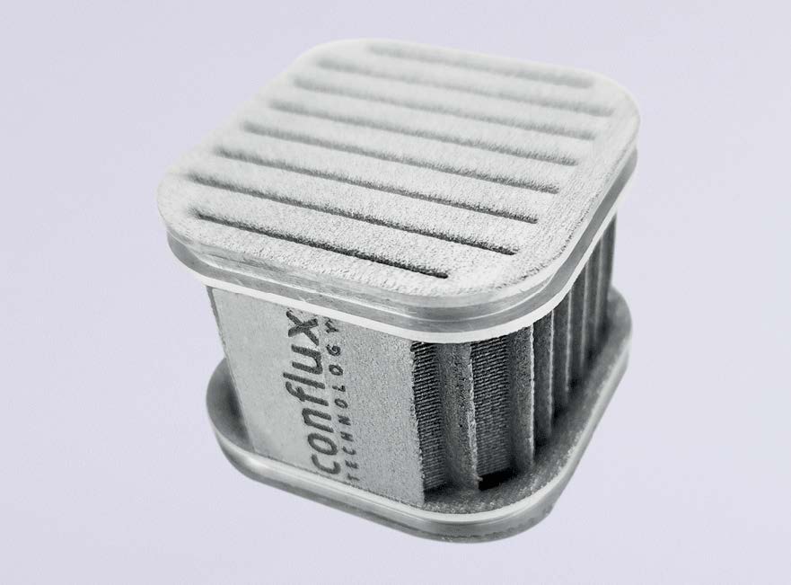
While there has been some exploration of additive manufacturing (AM) for compact heat exchangers (HX), development focus has rarely considered customisable or serviceable designs. The Conflux Cartridge heat exchanger is a complex 3D printed core, that can be embedded in a traditionally manufactured part or casing. The unique ‘cartridge’ for insertion features the patented technology of a Conflux CoreTM allowing it to be inserted into an external mechanism or casing.
Resulting in a compact, serviceable, customisable, and interchangeable form of heat exchanger that offers a multitude of benefits across a wide range of applications not limited to performance, integration, accessibility and maintainability. The balance of thermal and hydraulic performance for complex thermal systems through scalable and low-cost production make it ideal for small powertrain and energy systems. Furthermore, the ability to manufacture the cartridge heat exchanger in large batches with industrial DMLS machines keeps costs lower than equivalent traditionally manufactured options.
Objective: create a compact cartridge heat exchanger that delivers industry leading performance
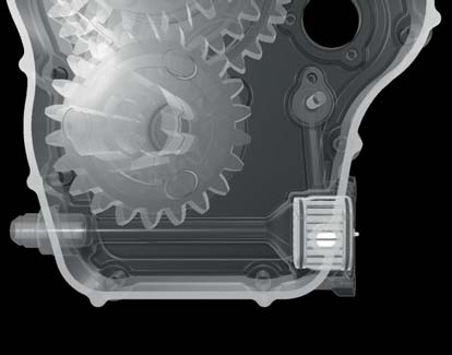
Our intention was to prove that the compact cartridge design of this heat exchanger could offer our customers unparalleled levels of customisability and serviceability not previously possible with more traditional HX design protocols. We also wanted to demonstrate that the production of the cartridge using additive manufacturing techniques would result in a more cost-effective outcome for the client. Specifically, we developed the cartridge HX for oil cooling applications in a gearbox but, in the process, we demonstrated that the cartridge design could be applied to other circumstances at a reduced price-point.
Design: Conflux CoreTM technology enabling serviceability and interchangeability
Challenge
To match or exceed an incumbent micro-tube heat exchanger for a transmission application at a significantly reduced price point. The following challenges needed to be met:
- Easy serviceability, interchangeability, and customisation
- Low-cost and low weight
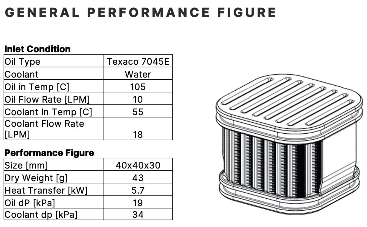
- Volume of 40mm x 40mm x 30mm to meet packaging requirements
- Achieve a heat transfer rate target of 5.7kW
- Maintain a pressure drop for the entire heat exchanger to less than 45kPa on the oil side and less than 50kPa on the water side
- Withstand an operating pressure of 600kPa
Solution
After setting the boundary conditions we undertook a detailed design of the HX cartridge core, involving a variety of calculations to better understand the design requirements and sensitivities that differing parameters had on performance. We used our design library of core geometries to test fin height, fin thickness, fin pitch and channel spacing to select a design that maximised heat transfer while minimising pressure drop.
Simulation: utilising computational fluid dynamics for better refinement capabilities
Challenge
There were two primary challenges during simulation. Firstly, to confirm that the selected core geometry performed in maximizing the heat transfer while minimizing pressure drops. Secondly, to accurate consider the impact of manifolds in calculating pumping requirements.
Solution
Core geometry performance
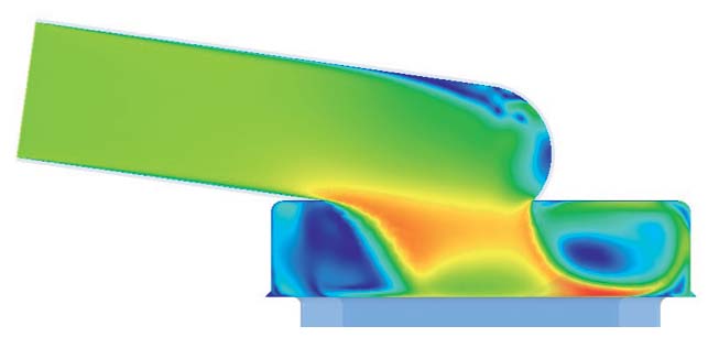
The initial geometry was used to perform computational fluid dynamics (CFD) simulations. With these, the heat transfer rate and pressure losses associated with the HX core could be better estimated. This was undertaken using Ansys Fluent on an in-house high performance computing cluster optimized specifically for CFD simulations. Meshing is a necessary step in the CFD process. This is where all solid and fluid domains are broken up into a huge number of smaller domains from which a numerical solution can be found. A good quality mesh is required to ensure the stability and accuracy of the results. The mesh was generated based on standard meshing practices.
Inflation layers were built on the no-slip walls, and sizing controls ensured good mesh metrics. Appropriately scaled boundary conditions were used for the simulation. Additionally, various contours and vectors of temperature, pressure and velocity were generated to assess the core performance in a greater depth of detail. These CFD simulations gave insights into performance for further refinements that could not be attained through spreadsheet calculations.
Manifold impact
Manifolds are required to accept the fluid inlet streams, and then direct them through the core of the heat exchanger and into the outlet fluid streams. Given manifolds add to the fluid pressure losses through the heat exchanger, they must be considered when calculating pumping requirements. Our CFD engineers performed porous media modelling to assess the pressure drops associated with the manifolding, and any implications of this.
Manufacturing: optimal printing strategies create new opportunities for scale of production
Challenge
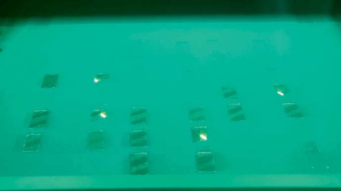
To accurately print gas-tight cartridges whilst maximising space on the build plate to achieve scale of production and cost targets.
Solution
In this instance we used aluminum (AlSi10Mg) for its low density and favourable thermal conductivity as our printing material. By implementing our design guides, we were able to help avoid the need for supports during the design phase. The CAD model was imported into our AM software to allow the part to be built layer-by-layer. At this point minimal support structures were added to assist the build and various printing orientations were considered to optimise the build process. We developed optimal printing strategies that nested many cartridges to be built on a single plate, providing a significant reduction in production time when compared to traditional manufacturing processes.
During post-processing we removed the cartridges from the build plate and conducted our proprietary de-powdering process to ensure the internal channels were clear and powder free. To verify gas-tight walls the part was submerged in water, and leak tested with compressed air. After post-processing, we inspected the cartridge using a portable measuring arm scanner to ensure dimensional accuracy. The resulting scans were compared to CAD data with a high degree of dimensional accuracy. This process can also be used to ensure mating surfaces and mounting locations are within specified tolerances.
Results: an accessible cartridge heat exchanger for a range of applications
Once post-production was completed, we engaged an independent and accredited test facility to validate thermal and hydraulic performance of the cartridge heat exchanger. Physical testing is an important validation step that not only confirms the performance of the design but can also be used to correlate simulation models. The heat transfer rate measured from the test rig was 5.7kW – this closely matched the predictions from the CFD models, validating the design methodology.
It also reached the target performance of 5.7kW. The pressure drop measured on the oil side of 35kPa closely matched the expected value of 34kPa from the simulations, while also being well below the maximum allowable value of 45kPa. The pressure drop measured on the water side of 45kPa deviated from the expected value from simulations, however was still below the maximum allowable value of 50kPa. The resulting cartridge was also very light – with a dry and wet weight of 43g and 60g, respectively. Due to the nature of AM, the design can also be easily changed based on customer requirements.
For example, if the fluid is altered then the cartridge can be reconfigured. Since different fluids have different properties, it may be advantageous to produce a new design specifically optimised for that fluid. This is far easier to perform with AM than traditional methods that require jigs, assemblies and so forth. We were pleased to find that the cartridge was easy to install and maintain. The housing could be simply opened, the cartridge removed, serviced as required, and then replaced. This could prove beneficial for fluid applications with particles or possible contaminants.
While this cartridge was produced for oil cooling, the design is not limited to oil, water or even liquid applications (the internal geometry can be changed for gas flow if required). The cartridge HX can be considered for a broad range of applications – transmissions for electric and combustion engines, power steering, battery thermal management, EV motor cooling, hydrogen systems, refrigeration and many more.
About this Technical Story
This Technical Story was first published in Heat Exchanger World Magazine in March 2024. To read more Technical Stories and many other articles, subscribe to our print magazine.
Technical Stories are regularly shared with our Heat Exchanger World community. Join us and share your own Technical Story on Heat Exchanger World online and in print.

