
In over 40 years of SACOME’s history, the company has supplied thousands of equipment for multiple and various applications. This article outlines some of the most common mistakes made during the installation and commissioning of heat exchangers that can negatively affect equipment performance and, in some cases, lead to complete failure.
By Fernando Vera, Technical Department, SACOME
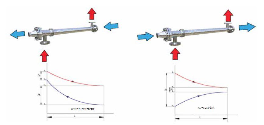
1. Wrong flow configuration of the fluids in the heat exchanger
According to the flow directions of the hot and cold fluid flow in a unit, there are 2 ways to install a heat exchanger, as shown in Figure 1. Except in some very specific applications, a heat exchanger has higher efficiency when installed in countercurrent configuration, since this arrangement results in a higher logarithmic mean temperature difference (LMTD) between the hot and cold fluid, resulting in higher thermal efficiency and, therefore, a smaller required heat exchange surface. However, in some specific processes a co-current arrangement may be preferable, so at the design stage, the Technical Department will recommend to the client the best solution for their particular case. When the customer proceeds with the installation and commissioning of the equipment, they may arrange the service inlets and outlets incorrectly by mistake. In that case, the equipment may finally be installed in co-current instead of countercurrent, which, for the reasons explained above, may have a negative impact on the performance of the heat exchanger.
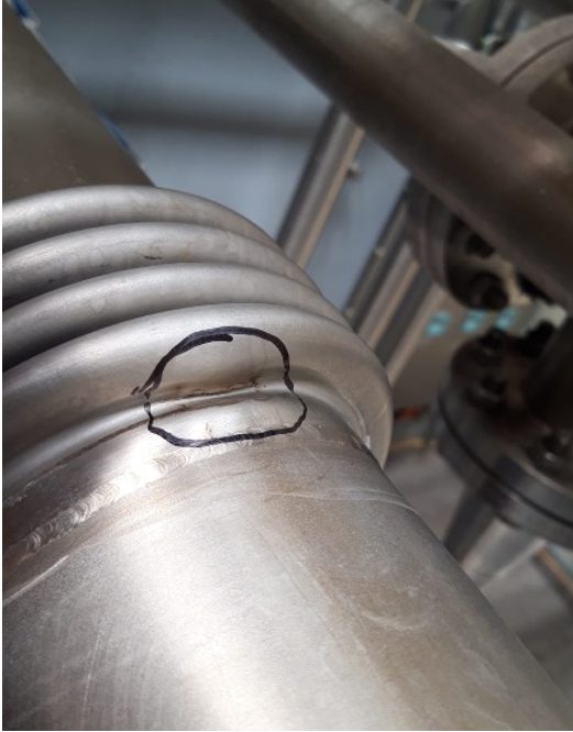
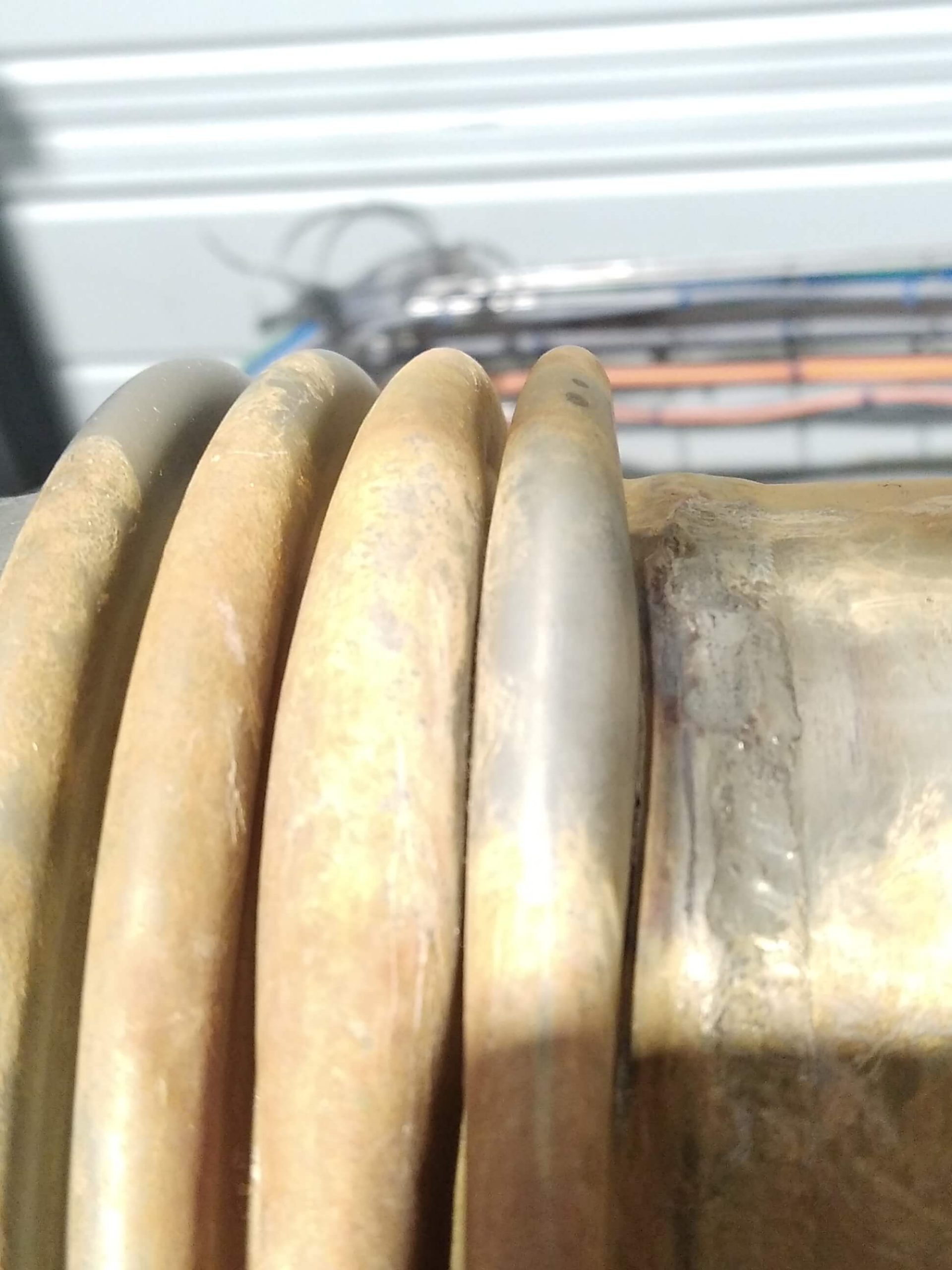
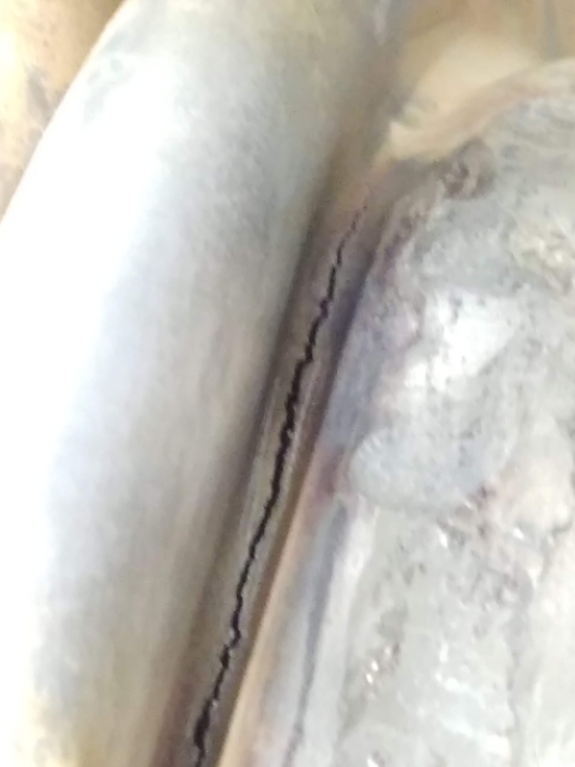

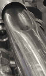
Figures 2, 3, 4 and 5. Examples of expansion joints collapsed and cracked by an overpressure in shell side.
2. Overpressures due to a close water loop with a bad design
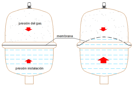
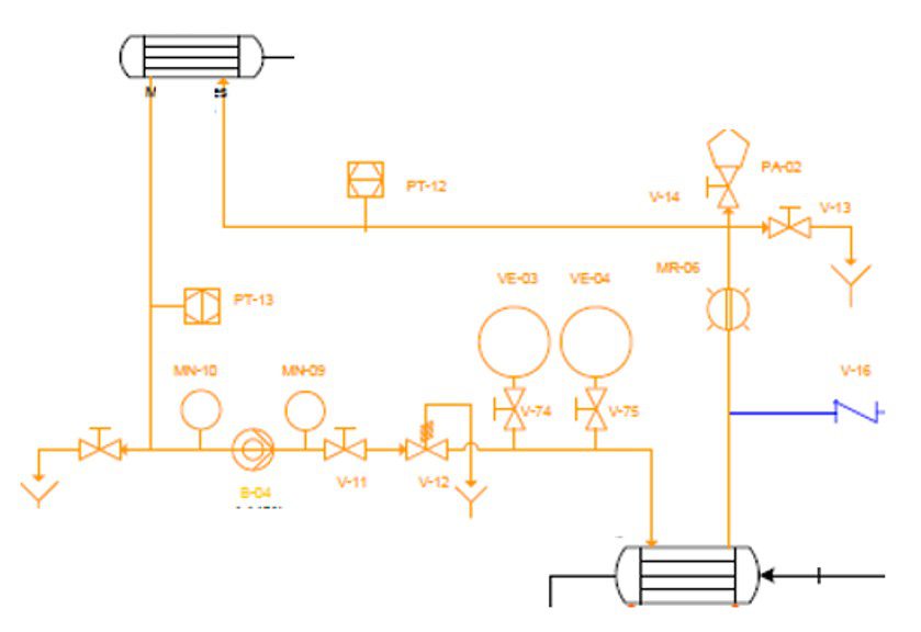
There are numerous reasons why unusual overpressure may appear during the operation of a tubular heat exchanger, such as water hammer or overheating of one of the fluids, among others. This overpressure can lead to plastic deformation, partial or total failure of the shell or inner tubes, or collapse of the bellows, which can render the equipment completely useless. On Figures 2, 3, 4, and 5 you can see typical failures of heat exchangers by collapse of the shell side, particularly of the expansion joint, due to overpressures in the service side. In the case of overpressure in a poorly designed hot water circuit, it is essential to install an expansion vessel or tank in the closed water loop. This component has the function of absorbing the pressure increase of the heat transfer fluid (for instance water or glycol/water solutions) when it heats up. This fluid, as its temperature increases, tends to increase its volume, and if the liquid is in a closed circuit and there is no component that can absorb this expansion, significant overpressure will appear, which can lead to the collapse of elements such as the expansion joint or the inner tubes of the heat exchanger. Figure 7 shows a typical diagram of a closed water loop where, among other necessary components such as pumps, pressure gauges, valves, drains, and sight glasses, the expansion vessel or tank can be seen.
3. Blocking of supports
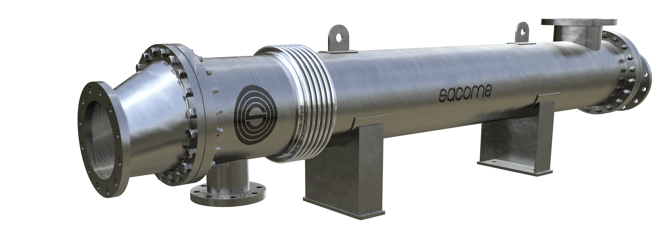
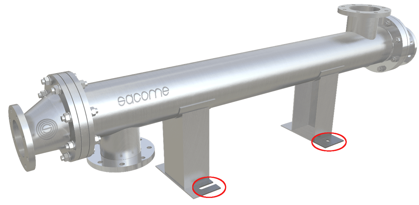
Depending on the disposition of the equipment (horizontal, vertical installation, one or several modules in series, etc.), the heat exchanger may be supported on the foundation in various ways. For example, in the case of a single module with horizontal layout, it can be supported on 2 cradles or support legs, as shown in Figure 8. If the anchor bolts are anchored to the floor in such a way that they do not allow movement of the equipment, there will be additional stresses in the expansion joint as well as in the tube-to-tubesheet weldings, thus leading to cracking in the welds. With this in mind, if the heat exchanger is fixed at 2 points, it is advisable to leave one of them sliding or allowing free expansion. In many projects the support or frame is part of the scope of supply, in which case this type of construction detail must be taken into account. However, if this is not the case and the customer decides to construct it themselves, it is essential that the installation company in charge of the frame take this type of detail into account, in order to avoid additional stresses (and possible breakage) in the equipment.
4. Poor design of the condensates pipeline
In a condenser or water/steam exchanger, if the condensate removal is not carried out properly, the shell side may start flooding, causing the steam stream to hit the liquid layer, thus causing loud noises and vibrations. To detect this malfunction, it is sufficient for the operator to touch the top and bottom of the heat exchanger in operation. If the top part is hot while the bottom is cold, the shell side is probably flooded up to the level where the surface temperature changes. This malfunction is known as water hammer, and it is one of the typical cases in a process line.
5. Excessive fouling
Fouling is a phenomenon that has a negative impact on the heat transfer coefficient, increases pressure drop, and can even activate and accelerate corrosion attacks. There are different fouling mechanisms: crystallization (typical in very hard water with high mineral salt contents, such as calcium carbonate and lime), sedimentation (deposition of sand, rust, or other suspended solids), chemical (in processes where the product can be degraded by temperature), freezing (when a fraction of the product is frozen by the process temperatures), biological (when untreated water is processed, thus enabling the proliferation of different types of organisms or microorganisms), and protein precipitation (typical in milk by-products), among others.
Given the complex nature of this phenomenon, the solution is often not trivial either and usually involves different aspects. With the aim of minimizing the problem and increasing the running time between CIP, the following actions can be taken:
• When doing the thermal calculation, a high overdesign can be considered or fouling factors can be introduced as a safety factor. This will give the equipment a margin to become fouled and still reach the required temperatures.
• Make the more fouling fluid flow through the tube side, as it is easier to clean than the shell side.
• Design the equipment to ensure a high process velocity for the process fluid, thus minimizing fouling.
• Provide a flanged tubesheet design so that the reducer or header can be easily removed with the aim of inspecting the tube side.
• In case a dirty fluid is flowing through the shell side, a solution with removable tube bundle can be suitable.


6. Corrosion attack due to the use of very aggressive cleaning agents
Fouling in a heat exchanger is a complex phenomenon that can lead to different types of dirt build-ups and deposits, such as oil and grease deposits, lime scale, different types of organic deposits, sludge, or metal oxides. In case of chemical cleaning (Cleaning-in-Place or CIP), cleaning solutions with different agents and concentrations can be used, such as hydrochloric acid (HCl), phosphoric acid (H3PO4), nitric acid (HNO3), citric acid (C6H8O7), caustic soda (NaOH), and different polyphosphates (such as NaPO4 or Na3PO4). Some of these agents are very aggressive and, in addition to the temperatures at which such chemical cleaning is usually carried out (typically between 60°C and 80°C), can lead to corrosion problems (uniform or localized, such as pitting or crevice corrosion) in the construction material of the heat exchanger.
The following are some basic guidelines to keep in mind when it comes to CIP cleaning:
- Check with a specialist company about the cleaning agents and concentrations to be used, aswell as the cleaning procedure, taking into account the construction material of the heat exchanger, both tubes and gaskets.
- Only circulate cleaning agents and concentrations according to the recommendations of this specialist company. Products such as hydrochloric acid (HCl), phosphoric acid, and nitric acid, among others, can be very aggressive at high temperatures.
- At the end of the chemical cleaning cycle, the heat exchanger should be rinsed with water. Otherwise, the solution may settle and in certain areas of the equipment the concentration of the cleaning agent may increase, raising the risk of corrosion.
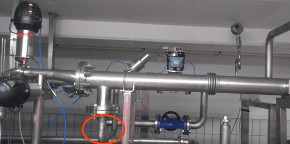
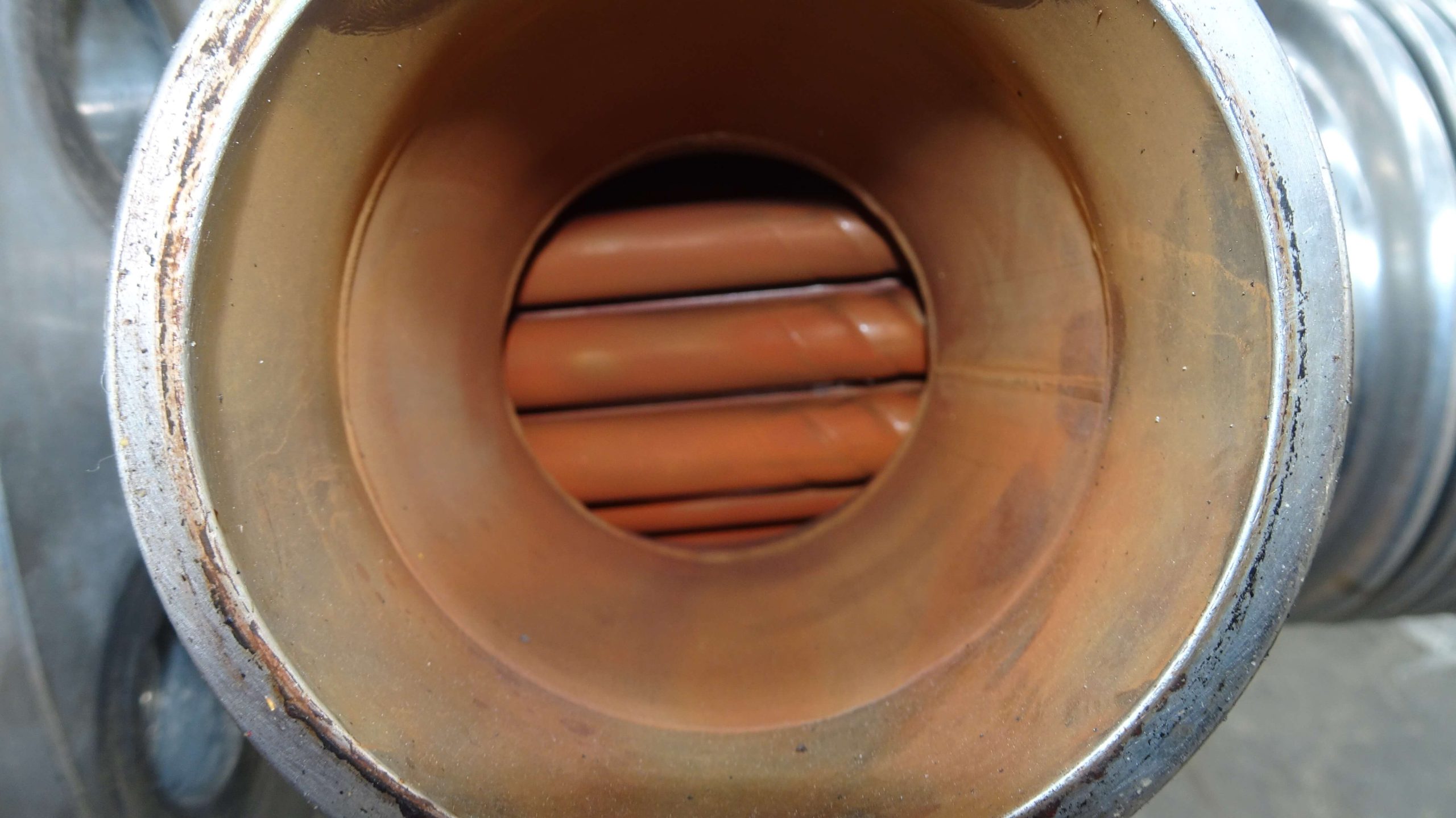
7. Corrosion due to use of service water with high chlorides content
Sometimes the customer uses untreated or poor quality service water with high ppm of salts
and chloride ions, which, together with elevated process temperatures, can lead to localized corrosion if the quality of the used stainless steel is not suitable. On Figure 13 you can see the shell side inlet nozzle of equipment with hard service water having high ppm of Cl-, which has caused high fouling as well as initiated corrosion of the pipes.
8. Freezing of product
During the shutdown of the installation, if the units are not completely drained, leaving fluid inside, and the ambient temperature drops below 0°C, there is a risk of freezing of the stagnant product, which can damage the heat exchanger tubes. This is the reason why it is recommended to place drain valves at the lowest points of the installation. On Figure 14 you can see a heat exchanger collapsed by water that has been retained inside and that has frozen when the temperature drops below 0°C. Another possible alternative is to use propylene glycol solutions in a suitable proportion, with a lower freezing point than water.
 About the autor
 About the autor
Fernando Vera is an Industrial Engineer from UPCT (Polytechnic University of Cartagena). With over 20 years of experience in process engineering at SACOME, where he has been part of the Technical Department and has held various roles since 1998, Fernando is an expert in the thermal and mechanical design of tubular heat exchangers. He works closely with both European and global markets, providing technical support and engineering solutions tailored to international clients. Fernando is fluent in 6 languages, which enables him to communicate effectively and build strong professional relationships worldwide. You can contact Fernando Vera directly by email at fvera@sacome.com or through his LinkedIn profile.
About this Technical Story
This Technical Story was first published in Heat Exchanger World Magazine in September 2025. To read more Technical Stories and many other articles, subscribe to our print magazine.
Technical Stories are regularly shared with our Heat Exchanger World community. Join us and share your own Technical Story on Heat Exchanger World online and in print.