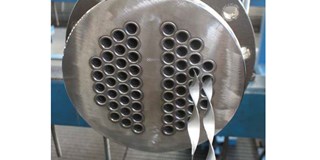
^ Tube bundle heat exchanger – Outside view.
Article By Peter Staub and Martin Paul, AURA GmbH & Co. KG, Germersheim, Germany
___
Heat transfer media based on organic fluids, so-called thermal oils, are used worldwide in a wide variety of areas. Their greatest advantage is the significantly lower required operating pressure compared to conventional, steam-based heating systems. In the temperature range from 200°C to 400°C, a superimposed pressure that is lower by a factor of 10 is no exception, which leads to significantly more cost-effective solutions.
Another advantage is that thermal oils can be used over a wide temperature range even at constant system pressure. A combined heating and cooling system, in which a central thermal oil circuit connects several consumers, boilers and cooling units with each other, can often noticeably reduce the number of required apparatuses and the length of the required piping system and often represents the economically most favourable option.
A disadvantage of these systems with thermal oil is the high dependency of the heat transfer on the heat transfer medium temperature. While water flows practically unchanged even near its freezing point, a noticeable increase in viscosity occurs with organic fluids at low temperatures. The heat transfer medium becomes more viscous, which has a negative effect on the heat transfer coefficient. This problem is typically more severe the greater the difference between the highest required heating temperature and the lowest required cooling temperature.
If, for example, a typical heat transfer tube through which the high-temperature thermal oil Mobiltherm 605 flows is considered at a temperature of 40°C and an average flow velocity of 1.5 m/s, the heat transfer coefficient is just 210 W/(m2 K). As a result of this low value, a very large heat exchanger would be required for a given cooling capacity, in order to compensate for the low coefficient with a larger exchanger surface. This leads to high investment costs.
Exactly in such cases, turbulence generation using twisted tape inserts (so-called turbulators) inserted into the exchanger tubes is a favourable option to significantly improve the heat transfer, keep the required heat exchanger area small and thus minimise the investment costs.
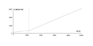
Fig. 1 shows the heat transfer coefficient as a function of the Reynolds number, which characterizes the flow, for the case under consideration. Up to a Reynolds number of 10.000 the course can be divided into two areas, the area of purely laminar flow on the left and the transition area between laminar and turbulent flow on the right. In our example, the Reynolds number is just over 800, i.e. in the laminar range.
The basic idea of using turbulators is to increase the degree of turbulence in such a way that the transition area on the right is reached and thus the transition coefficient is increased accordingly. Turbulators increase the turbulence via various mechanisms.
On the one hand, they increase the mean flow velocity of the flow, one of the most important influencing variables. They reduce the free cross-sectional area so that the speed increases for the same volume flow. In addition, due to the shape of the plates, the flow must travel a longer distance along the pipe, which in turn leads to an increase in speed. On the other hand, the twist favours the change of the laminar boundary layer to a turbulent one. The thermal boundary layer between the inner wall of the pipe and the main flow, which is responsible for heat transport between the exchanger pipe and the heat transfer medium, is thus reduced, which in turn increases the overall convective heat transfer.
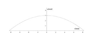
Furthermore, the spiral sheet significantly changes the velocity profile. Fig. 2 shows the profile in the unmodified tube. The flow (u) is pronouncedly laminar and the characteristic parabolic shape is uniform. At the pipe walls the flow comes to a standstill due to adhesive forces, in the middle the velocity reaches its maximum.
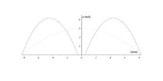
Fig. 3 shows a numerically determined velocity profile after insertion of a spiral sheet. Even when calculated assuming a laminar flow, the differences are clearly visible. Since adhesive forces on the spiral sheet surface also slow down the fluid molecules to a standstill, the profile is divided into two areas. The maximum occurring velocity is significantly increased, as is the velocity gradient, especially at the inner wall of the pipe. This improves the convective heat transfer coefficient.
In our example, the heat transfer coefficient can be almost quadrupled by inserting turbulators with a pitch of 180°/100mm, thus increasing the required heat transfer surface by almost the same factor.
Turbulators therefore have a significant influence on heat transfer without requiring complex conversion. They are efficient, simple measures to increase heat transfer. Their disadvantage, a slightly higher pressure drop, can often be more than compensated for by the cost savings achieved by more compact heat exchangers.
^ Tube bundle heat exchanger – Outside view.
Article By Peter Staub and Martin Paul, AURA GmbH & Co. KG, Germersheim, Germany
___
Heat transfer media based on organic fluids, so-called thermal oils, are used worldwide in a wide variety of areas. Their greatest advantage is the significantly lower required operating pressure compared to conventional, steam-based heating systems. In the temperature range from 200°C to 400°C, a superimposed pressure that is lower by a factor of 10 is no exception, which leads to significantly more cost-effective solutions.
Another advantage is that thermal oils can be used over a wide temperature range even at constant system pressure. A combined heating and cooling system, in which a central thermal oil circuit connects several consumers, boilers and cooling units with each other, can often noticeably reduce the number of required apparatuses and the length of the required piping system and often represents the economically most favourable option.
A disadvantage of these systems with thermal oil is the high dependency of the heat transfer on the heat transfer medium temperature. While water flows practically unchanged even near its freezing point, a noticeable increase in viscosity occurs with organic fluids at low temperatures. The heat transfer medium becomes more viscous, which has a negative effect on the heat transfer coefficient. This problem is typically more severe the greater the difference between the highest required heating temperature and the lowest required cooling temperature.
If, for example, a typical heat transfer tube through which the high-temperature thermal oil Mobiltherm 605 flows is considered at a temperature of 40°C and an average flow velocity of 1.5 m/s, the heat transfer coefficient is just 210 W/(m2 K). As a result of this low value, a very large heat exchanger would be required for a given cooling capacity, in order to compensate for the low coefficient with a larger exchanger surface. This leads to high investment costs.
Exactly in such cases, turbulence generation using twisted tape inserts (so-called turbulators) inserted into the exchanger tubes is a favourable option to significantly improve the heat transfer, keep the required heat exchanger area small and thus minimise the investment costs.
Fig. 1 shows the heat transfer coefficient as a function of the Reynolds number, which characterizes the flow, for the case under consideration. Up to a Reynolds number of 10.000 the course can be divided into two areas, the area of purely laminar flow on the left and the transition area between laminar and turbulent flow on the right. In our example, the Reynolds number is just over 800, i.e. in the laminar range.
The basic idea of using turbulators is to increase the degree of turbulence in such a way that the transition area on the right is reached and thus the transition coefficient is increased accordingly. Turbulators increase the turbulence via various mechanisms.
On the one hand, they increase the mean flow velocity of the flow, one of the most important influencing variables. They reduce the free cross-sectional area so that the speed increases for the same volume flow. In addition, due to the shape of the plates, the flow must travel a longer distance along the pipe, which in turn leads to an increase in speed. On the other hand, the twist favours the change of the laminar boundary layer to a turbulent one. The thermal boundary layer between the inner wall of the pipe and the main flow, which is responsible for heat transport between the exchanger pipe and the heat transfer medium, is thus reduced, which in turn increases the overall convective heat transfer.
Furthermore, the spiral sheet significantly changes the velocity profile. Fig. 2 shows the profile in the unmodified tube. The flow (u) is pronouncedly laminar and the characteristic parabolic shape is uniform. At the pipe walls the flow comes to a standstill due to adhesive forces, in the middle the velocity reaches its maximum.
Fig. 3 shows a numerically determined velocity profile after insertion of a spiral sheet. Even when calculated assuming a laminar flow, the differences are clearly visible. Since adhesive forces on the spiral sheet surface also slow down the fluid molecules to a standstill, the profile is divided into two areas. The maximum occurring velocity is significantly increased, as is the velocity gradient, especially at the inner wall of the pipe. This improves the convective heat transfer coefficient.


