Bolted flange joint connections should not leak on heat exchangers, but they often do because of design and / or assembly issues. However, by giving proper attention to the factors that most significantly influence bolted assemblies, it is possible to achieve leak-free connections on heat exchangers. By following guidelines spelled out in ASME PCC-1, utilizing certified and experienced bolting personnel, and implementing some shared best practices based on years of field experience, this article provides useful insights and suggestions for consideration related to minimizing leaks on heat exchangers.
Mike Prevost (VP Specialty Services – Ohmstede Industrial Services, Inc.)
Scott Hamilton (CEO and Founder – Hex Technology)
Many end users assign a level of criticality to their bolted fl ange joint assemblies. A common practice is to separate fl ange joints into three classifi cations: Mild, intermediate, and critical service.
Because of the degree of temperature and pressure involved with heat exchangers, the lowest rating they’ll typically be assigned is intermediate. Indeed, most exchangers qualify as critical. Despite this classification and the increased at-tention that logically should follow it, heat exchangers are a common source of flange leaks. How can heat exchanger joints be so important, yet so troublesome?
First, let’s examine the situation through the lens of Risk-Based Inspection (RBI). Under this approach, a connection is deemed more or less critical depending on two factors:
1. Probability of Failure (PoF), or the likelihood of leaking
2. Consequence of Failure (CoF), of the potential for harm/damage if a leak occurs, or if the equipment is taken offl ine.
High temperatures, pressures, and low gasket stresses are typically associated with heat exchangers. Therefore, the CoF on these joints is higher than what we expect on typical B16.5 flanges.
Teamwork with an inherent burden on assemblers
Joint assembly is a team effort that involves many more people than just the crew putting their hands on the flange itself. The two groups of people with the most infl uence on the quality of the outcome are Engineering and Assembly teams.
Let’s imagine that these two teams were working on the joint in a classroom setting. Each can earn up to 50 points. Working together, they need to score 80% or better to achieve a leak-free seal.
This design problem happens because exchanger design codes don’t take ASME PCC-1 Appendix O calculations into the equation. The discussion of gasket stress vs. bolt stress could be the basis of an entirely different article, but some key points are:
1. The bolting industry has been trained for decades to think bolt stress is more critical than gasket stress. Improper or unbalanced gasket load is re-sponsible for the great majority of all fl ange leaks.
2. Appendix O is a comparatively new way to calcu-late bolt load based on the resulting gasket stress.
3. Because Appendix O of PCC-1 has only been around for 10 years, not all design codes have been updated recently or thoroughly enough to use it.
Bottom line: Even with excellently planned engineer-ing, joints around heat exchangers are under-designed. To return to our classroom analogy, imagine that the engineers were constrained to only score 40 or even 30 out of 50.

The result: Assemblers have to score near-perfect on their responsibilities for the team to achieve a passing score (and, thus, for the fl ange to be leak-free).
A typical response to this situation is for engineering to attempt to make up for the defi cit through lengthier procedures. However, here is a truth all engineers and maintenance leadership must keep in mind: You cannot out-procedure a lack of training.
The way to ensure proper assembly is not to hand your craft lengthier documents – which inherently makes them harder to read and therefore easier to ignore. Instead, the need is for a program that teaches assemblers what good, bad, and ugly looks like in the field, verifying their competency through hands-on techniques.
What’s a good heat exchanger joint assembly process?
The 4-effect evaporator plant with TVR has an evaporation capacity of around 4.8 m3/h and was normally operated for a period of 12 to 15 days and shut down for 5 to 7 days for cleaning with a high pressure water jet. Post-cleaning the plant runs at 80% of the capacity on day 0 and the capacity drops to 50% before the next cleaning. From the operational experience of this multi effect evaporator plant the 1st effect with a steam temperature of 115oC is the heat exchanger which encounters the most fouling and is the limiting factor for operation of the entire plant. The subsequent effects of the MEE plant also encounter fouling but lesser as compared to the first effect of the plant.
The right amount of gasket compression
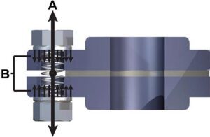
Bolts (a.k.a. studs) have an elastic property, which allows them to work as springs to compress the flanges together on the gasket. When load is applied, it stretches the bolt, which then tries to return to its original length. This creates compressive force across the joint members. See how a fastener acts as a spring to compress the gasket between two flanges in the diagram below (see figure 3).
Bolted fl ange joint assemblies create a “Clamping Force” across the joint surface that applies gasket stress or compression suffi cient to maintain a seal during normal operating conditions.
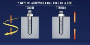
Torqueing and tensioning are two different methods for achieving an axial load on the bolt. Torqueing uses the turning of the nut to stretch the bolt. Tensioning uses different tooling that stretches the bolt without requiring the turning of the nut to achieve the bolt load, as illustrated above (see fi gure 4).
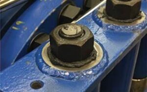
Proper lubrication is severely undervalued in bolted assembly. Perhaps no other practice is so simple yet wields so much infl uence over the fi nal result. A sufficient amount of lubrication reduces friction and allows the applied bolt load to generate better clamping force. Meanwhile, improper lubrication (or having no lubrica-tion at all) creates an additional variable detrimental to the final result since most engineering calculations for bolt load assume proper lubrication. Additionally, proper lubrication can reduce the potential for “galling,” or the fasteners becoming stuck or stripped in later disassembly. The image below (see figure 5) shows a proper amount of lubrication applied to a bolt. Note how a bead of lube “squishes” out from beneath the hand-tightened nut. An assembler should see such a bead after hand-tightening if they have applied lubricant correctly.
Gasket selection is also essential. A Double Jacketed gasket has been the staple for heat exchanger gaskets for years. However, we have seen that Kammprofile gaskets have produced better results in most cases. Manipulating the area of the Kammprofile gaskets allows for proper gasket stress. By following the ASME PCC-1 (Appendix A) to train bolting personnel, owners can dramatically improve the likelihood of achieving leak-free exchangers.
Hard-won lessons in heat exchanger flange assembly
Hex Technology has worked directly or consulted with hundreds of end user sites on thousands of heat exchangers worldwide. While the totality of those lessons would be impossible to document in a single article, some key lessons apply broadly to most units, which the readers of this magazine may fi nd helpful. They are:
Plate heat exchangers
 Plate heat exchangers require rubber gaskets, which cannot withstand the amount of gasket stress that a Kammprofile or a Spiral Wound Gasket (SWG) can withstand. These rubber gaskets are relatively easy to over-compress; and as a result, it is easy to damage them. Therefore, assembly teams must obtain proper torque values from the manufacturer and work across the body of the exchanger in a crisscrossed pattern.
Hairpin Heat Exchangers
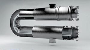 Bolted flange joints on Hairpins are often not so well designed as they ought to be and are prone to leakage as a result. Manufacturers often prescribe higher torque values to make up for this deficit.
Air-Cooled (a.k.a. “Fin Fan”) Heat Exchangers
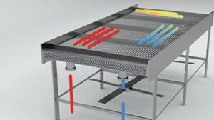 Typical maintenance on an Air-Cooled Heat Exchanger includes removing plugs, replacing them, and then reinstalling them into the header box. This process is trickier than it sounds. The #1 rule for assemblers here should be: Do NOT use an impact wrench for assembly or disassembly. It is very easy to strip threads on these units, and experience proves they are more prone to galling. Proper lubrication should be considered a must on all assemblies. However, it is especially crucial on these units due to the potential for galling.
Shell and Tube sheet Heat Exchangers
 Shell and Tube sheet configurations are what assemblers see the most in the field. There are three key measurements teams need to be aware of when assessing these units:
1 Flange circumferential variation (T1), or the “rollout” on a flange. This refers to variations in height around the flange sealing surface.
2. Radial variation tolerance (T2),or what’s commonly referred to as “high-low.” T2 is the difference in height from the inside to the outside of a sealing surface.
3. Pass partition tolerance, which refers to height differences on any of the pass partitions within the flange.
 There are multiple complex methods for measuring these variations. However, the differentials are so small that it is difficult, if not impossible, to determine if the issue is within or outside of the accepted range with the naked eye. Therefore, if an assembly crew has any reason to believe there’s an issue with these surfaces, the best practice is to speak with a super-visor and bring in a machining tool for a proper analysis.
Conclusion
Flange joint connections are dynamic, but with proper understanding, management, and application, there are many opportunities to achieve leak-free performance on exchangers. By following the ASME PCC-1 guide-lines and using qualified bolting personnel, the odds of achieving leak-free exchangers improve dramatically. From a technical and application perspective, the authors and their respective companies remain committed to providing the support necessary to help avoid leaks. We invite readers to receive free training on Heat Exchanger Assembly through Hex Technology’s online learning platform. Sign up at hextechnology.com and to discover how they can manage all bolted flange joint assemblies utilizing Ohmstede Industrial Services.
References:
ASME PCC-1 (2019) Jet-Lube – See website for MSDS
About the authors
 Ohmstede Industrial Services, Inc. can provide ASME PCC-1 trained personnel for bolted flange joint assemblies for exchang-ers and piping.Mike Prevost has over 30 years of experience in the oil and gas business. He has worked with bolted flange joint connections for well over 15 years. For more information email Mprevost@ohmstede.net
 Hex Technology, LLC is a technology-based company specializing in the science and training of bolted flange joint connections. Scott Hamilton has a passion for bolting and for making bolted flange joint training accessible to everyone. He has a staff of experienced and committed people who bring the field to the classroom – the training is down to earth, practical, and technically accurate. For more information email Scott@hextechnology.com
About this Featured Story
This Featured Story was first published in the December 2021 issue of Heat Exchanger World Magazine. To read more Featured Stories and many other articles, subscribe to our print magazine.
Featured Stories are regularly shared with our Heat Exchanger World community. Join us and share your own Featured Story on Heat Exchanger World online and in print.


