Vapor infusion is an antifouling technology that reduces fouling and carbon expression through creation of a chemically and mechanically induced nanobubble formation. This article reviews vapor infusion and nanobubble science, development, and commercial application.
By Michael Radicone, HTRI
The issue
Cooling water used in the heat exchange processes may contain dissolved, sedimentary, or planktonic fouling agents. They will attach to heat transfer surfaces, forming intrusive, insulating beds through adhesion and solidification that impede water fl ow and heat transfer. This type of fouling impacts the mechanical or electrical system associated with the heat exchanger. Responding to reduced heat transfer or elevated pressure drop often means compensatory action to increase water fl ow, which in turn necessitates additional energy draw that, through fuel burn, elicits elevated carbon presentation. Greenhouse gases including carbon dioxide, sulfur dioxide, and others are released into the atmosphere through energy generation. Higher greenhouse gas concentrations in the atmosphere capture solar energy and thus raise the earth’s temperature. Net Zero methods are intended to reduce greenhouse gas emissions from human activity. To achieve global Net Zero goals, companies need to reduce CO2 emissions, especially any “low hanging fruit” such as reducing energy waste by improving heat exchanger efficiency within their facilities.
Furthermore, the potential non-environmental benefits derived from functional improvement, such as cost or labor savings, contribute to a better value proposition. Heat exchangers are a vital component in most industrial process systems, and carbon expression associated with heat exchanger fouling could account for a significant amount of atmospheric discharge. Any achievable improvement could offer broad impactful environmental and energy saving benefits. Providing a sufficient water supply, without fouling, is key to this endeavor.
Fouling-greenhouse gas relationship
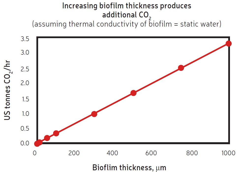
Studies have shown that fouling in a heat exchanger leads to additional energy demands and is directly related to greenhouse gas emissions[1], as indicated in Figure 1, and potentially to other environmental consequences. The loss of heat recovery and the additional energy for pumping represent a loss of thermal efficiency. The increase in energy supply, whether created on site or drawn from a local utility, is through additional fuel burn.
Nanobubbles
Nanobubbles are tiny vapor-filled structures with a diameter of less than about 1 µm and are potentially 2500 times smaller than a single grain of sand. Tens of millions fit within a micro bubble and offer an extremely large surface area. They may exist either as surface nanobubbles or dispersed in bulk liquid. Fluid-borne nanobubbles have a very long life in water due to their neutral buoyancy and low-rise velocity, possibly persisting for more than two months. Their characteristics are due to strong surface charges, internal pressures, and surface tension. Nano bubbles undergo Brownian motion within a fluid which enables them to continuously stimulate physical, biological, and chemical interactions and allow for a long perseverance within a fluid.
Nanobubbles have been shown to induce the removal of fouling mineral sites held together by minerals such as calcium carbonate and provide the cleaning of stainless-steel surfaces. Nanobubbles were determined to alleviate and resolve pitting caused by sulfate-reducing bacteria with pipe sections and service water from the secondary cooling water system at Three Mile Island Nuclear Power Station. After eight months of exposure, the pipe samples were sectioned and examined to measure corrosion pit depth. The results revealed that the mean pit depth was approximately 50% greater in the control pipe (which did not receive nanobubbles) than in the sample exposed to nanobubbles.
Vapor infusion nanobubble formation
Fabric expansion joints are critical components in industrial ductwork systems, providing flexibility To generate nonspecific high-volume bulk fluid nanobubbles for use in large commercial applications such as antifouling in heat exchangers, various methods have been utilized. These include excessive energy and water required methods such as flow generators that use membranes, static mixing, swirling liquid flow and pressurized dissolution to create nanobubble emulsions of significant density.
The task of treating cooling water in an environment such as a heat exchanger necessitates a simple, easily integrated approach. Vapor infusion is just such an approach and can form high nanobubble concentrations. Vapor infusion uses various methods to form nanobubbles, including mechanical, physical, and chemical means. These simple infusion techniques include bubble shearing, microbubble creation and collapse and use of varied gases create bubble surfaces prone to shrinking, prevent dissolved oxygen mass transfer, and provide a chemical treatment.
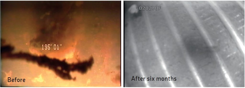
In 2005, a test of the technology was planned at the request of an electronics manufacturing plant that had a geothermal system suffering from severe biofouling in exchanger and recipient well screens, resulting in significant back pressure. The supply well water contained high levels of mineral iron and iron-reducing bacteria which caused fouling within the exchanger and downstream well screens over 2000 feet away. After installation of an infusion system, the heat exchanger showed improved function and the back pressure was resolved in two months. The well screen fouling was resolved after six months of vapor infusion. Photos taken of the well screens prior to infusion indicated significant, gelatinous biofilms but, after infusion, only sand silt remained (Figure 2). The well screens received only pre-infused water from the exchanger and not direct infusion. This client went 16 years without needing to clean their exchanger.
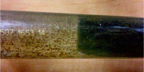
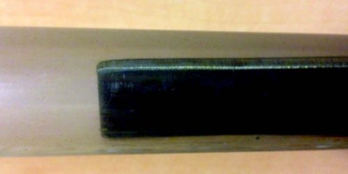
A further indication of downstream bubble interaction was provided during a US Navy trial. Naval Facilities Engineering Systems Command (NAVFAC) wanted to determine if vapor infusion could provide sustainable bubbles for downstream shipboard seawater piping systems. NAVFAC designed a proof-of-concept study which pumped seawater from the sea water surface off Kona, Hawaii. The test pipes were clear PVC and over twenty feet long. Normally, ambient air bubbles should have coalesced over this distance, providing little wall surface interaction. The researchers compared a timed iodine vapor infusion with a non-infused control.
After 45 days, the biofouling within the two pipes containing titanium coupons (as seen in Figures 3 and 4) are noticeably different indicating nanobubble formation. University evidence of nanobubble formation using vapor infusion treatment chemicals was provided by the Earthman Labs at the University of California (UC) Irvine, CA.[2] The purpose of the study was to determine if infusing iodine vapor into a fluid volume could create nanobubbles without the varied methods commonly used. Two infusion devices consisting of a simple ¼-in. OD tube and a custom injection quill were used to determine if microbubble size influenced nanobubble formation and their characteristics.
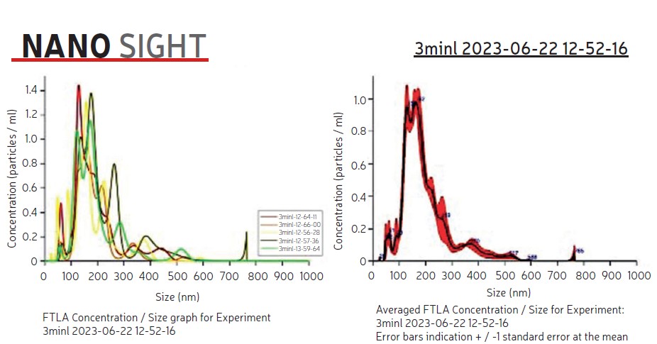
After three-minutes of infusion, the fluids were left untouched for a period to indicate if any nanobubbles persevered. The infused fluids were analyzed using a NanoSight device by Malvern Panalytical. to determine the concentration density of nanoparticles within the solution.
The results (Table 1) indicate that infusing for three minutes, using simple diffuser and vapor infusion treatments created a significantly high density of relatively small (under 200 nm) bubbles. Of significance was the persistence of bubbles 48 hours post-infusion, indicating the neutral buoyancy of the nanobubbles.
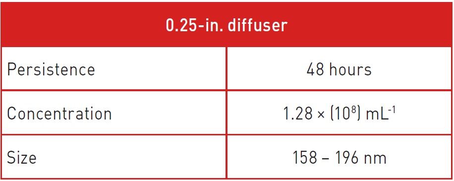

A snapshot of the nanobubble analysis seen in Figure 5 as provided by the NanoSight device clearly indicates bubble size and concentration. The analysis was conducted by Marco Ugalde-Valdés from Instituto Politécnico Nacional, Mexico City while visiting the Earthman Labs at UC Irvine. It is postulated that the vapor infusion treatment chemicals and shearing techniques facilitate the creation of microbubbles which shrink in size to nanobubbles. Vapor infusion currently uses elemental iodine, ammonium benzoate, and other vaporous chemicals, based on foulant type, system materials, and regulatory requirements.
Commercial application
Vapor infusion using chemical vapors in a manner as described in this article allows for the formation of bubble emulsions including nanobubbles of a desired volume and size for use in industrial settings. The vapor infusion system utilizes a chemical treatment in an easily replaceable cartridge. As oil-free air of a necessary flow rate and pressure is directed through the cartridge, the chemical vapor treatment moves with the airflow to the heat exchanger injection site. The chemical vapor flow is sheared by the infusion quill into the cooling water pipe before it enters the heat exchanger. The creation of smaller microbubbles due to shearing hastens the creation of nanobubbles for internal and downstream presentation. The bubble emulsion, including nanobubbles, moves through the heat exchanger. The nanobubbles move in a non-coalescing, Brownian motion driven cloud, contacting surfaces within the heat exchanger. As the nanobubble cloud makes contact, the bubbles interact with fouling agents on heat transfer surfaces while imparting the chemical treatment.
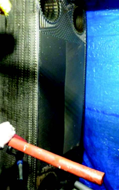
Vapor infusion occurs for a designed duration and frequency and does not require constant vapor presentation. The bubble emulsion then moves through the system for discharge. The results of several commercial applications bear out the efficacy of this protocol. In one such application, a Norwegian Cruise Line ship, was experiencing fouling within their engine coolers when infusion devices were installed. After installation the aft engine cooler plates were opened for inspection onboard (Figure 6) and clearly showed a lack of fouling after three years of infusion without any other antifouling treatment. During this time, the electro chlorination system was turned off. This system is in use on other ships for engine and flue gas scrubber applications with comparable success.
Conclusion
Nanobubbles can be produced by different methods, including vapor infusion, and have been shown to offer improvement in various waterborne fouling applications. Success in both laboratory and commercial settings makes it obvious that nanobubbles may have a stronger impact on heat exchanger fouling than first expected. Vapor infusion holds promise in maintaining heat exchanger performance and resultant environmental impact while being commercially acceptable. Research into application in wastewater treatment, flue gas scrubber function, and membrane fouling may lead to efficiency gains and improved environmental impact in areas other than heat exchangers. For further information please visit www.htri.net/vapor-infusion.
References
[1] Casanueva-Robles, T., and Bott, T. R., The environmental effect of heat exchanger fouling: A case study, in Proc. 6th Intl. Conf. Heat Exchanger Fouling Cleaning -Challenges and Opportunities, vol. RP2, eds.
H. Müller-Steinhagen, M. R. Malayeri, and A. P. Watkinson, pp. 278 – 282, ECI Symp. Ser., Kloster Irsee, Germany, 2005.
[2] M. Radicone, M.A. Ugalde-Valdés, J. Guzmán-Mendoza, and J. C. Earthman. Vapor Infusion with Nanobubbles to mitigate heat exchanger fouling and reduce its environmental impact. Proceedings of International Conference on Heat Exchanger Fouling and Cleaning, Lisbon, 2024
About the author

Michael Radicone is president and chief science officer of I2 Air Fluid Innovation and Specialty Product Lead for HTRI. At I2 Air Fluid Innovation, he has developed and patented technologies that address heat exchange fouling, toxic mercury presence in fluids, flue gas scrubber enhancement, medical and dental waterline microbial fouling and aortic catheter disinfection. As specialty Product Lead for HTRI, he oversees development and integration of the Vapor Nano Bubble Infusion technology. He can be reached by email at mike.radicone@htri.net
About this Technical Story
This Technical Story was first published in Heat Exchanger World Magazine in June 2024. To read more Technical Stories and many other articles, subscribe to our print magazine.
Technical Stories are regularly shared with our Heat Exchanger World community. Join us and share your own Technical Story on Heat Exchanger World online and in print.

