
In a high-pressure, high-temperature hydrogen service, the integrity of pressure equipment is critical to the safe and efficient operation of the plant. This is especially true in facilities where long-term exposure, material selections, and demanding operation converge to challenge design assumptions and inspection practices.
By M Norhisyam Awang, Principal Mechanical Engineer, and Nur Athirah Ishar, Staff Mechanical Engineer, PETRONAS
This paper presents a case study from an ammonia complex that has been operational since the late 1990s, focusing on recurrent cracks found in its Boiler Feed Water (BFW) Preheaters. These preheaters, constructed from 2 1/4Cr-1Mo low alloy material, are operating in high-temperature and high-pressure hydrogen service. Despite adhering strictly to the material selection and specifications outlined in API RP 934 and API RP 941, which align with the Nelson Curve operating limits, these units have consistently exhibited cracks in their thick-walled circumferential weldments. The cracks originated from the internal surface and, in some cases, propagated through the full thickness of the material. These recurring incidents have necessitated the removal of the affected equipment, underscoring the severity of the issue and the irreparable nature of the damage.
In response to the incidents, enhanced replacement strategies were developed with stricter fabrication and heat treatment protocols aligned with API RP 934-A standards. Advanced inspection techniques such as 100% Phased Array Ultrasonic Testing (PAUT) at all circumferential welds were implemented. This case highlights the importance of proactive assessments and stringent fabrication requirement and quality controls in maintaining plant reliability and efficiency.
Background
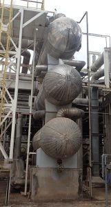
A high-pressure, high-temperature hydrogen production facility operates with multiple heat exchanger systems, including a set of three vertically stacked Boiler Feed Water (BFW) Preheaters in the ammonia synthesis section. These units, shown in Figure 1 — referred to as E-02A, E-02B and E-02C — are designed to transfer heat from synthesis gas to boiler feed water, significantly improving thermal efficiency of the process.
On the tube side, synthesis gas containing hydrogen enters at a temperature of 340°C and pressure of 190 barG. Simultaneously, boiler feed water enters the shell side at around 216°C and 130 barG. The exchangers’ function is to recover heat from the hot synthesis gas stream to preheat the feedwater for a boiler, thus recovering thermal energy and optimising process efficiency.
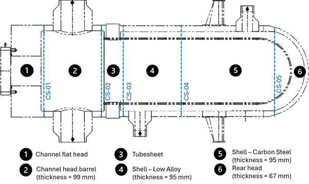
Each of these heat exchangers is constructed using low alloy material SA-336 F-22 Cl. 3 (2¼% Chromium, 1% Molybdenum) for the tube side, while the shell side is fabricated from low alloy of same specifications at the front and carbon steel SA-516 Gr. 70 towards the rear side. The tubesheet is also made from SA-336 F-22 Cl. 3 with an Inconel 600 overlay of 6 mm thickness for enhanced resistance against High Temperature Hydrogen Attack (HTHA). The detailed construction is illustrated in Figure 2.
The circumferential weldments discussed for the heat exchanger are as follows:
- CS-01 refers to the weldment between the channel’s flat head (item 1) to the channel head’s barrel (item 2), both fabricated from low alloy material.
- CS-02 refers to the weldment between the channel head’s barrel (item 2) and the tubesheet (item 3), also of the same low alloy.
- CS-03 refers to the weldment between the tubesheet (item 3) and the shell (item 4), which are also of the same low alloy.
- CS-04 refers to weldments between the shell courses (item 4 and 5), and are of different materials—low alloy steel and carbon steel, respectively—requiring careful consideration of dissimilar metal welding.
- CS-05 pertains to the weldments between the shell (item 5) to the rear head (item 6), both made of carbon steel, which is a relatively lower complexity compared to dissimilar metal and low alloy material joints.
These exchangers are designed in accordance with ASME BPVC Section VIII Division 2 (1995 Addendum) and follow TEMA Class R standards with a DEU-type configuration — characterised by a high-pressure closure and a one-pass U-tube bundle arrangement.
Problem statement
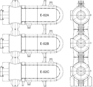
E-02A, at the top of configuration as shown in Figure 3, was the first unit to exhibit signs of degradation in 2010, after more than a decade in service. A leak was observed at CS02 circumferential weldment, indicating that a crack had propagated through the wall thickness. Based on the operational margin of the system and confirmation from Operations and Process teams, the unit was taken out of service while maintaining plant performance with the remaining two units, E-02B (middle) and E-02C (bottom).
Following the installation of the replacement unit for E-02A in 2012 (tagged as E-02A-01), all three heat exchangers continued operating without any incidents until the scheduled plant shutdown in 2018, during which, a proactive internal inspection was carried out on all CS01, CS02 and CS03 circumferential welds of the three units. During the inspection of E-02B, a transverse crack approximately 5 mm in length was identified near the 1 o’clock position at CS02. Additional cracks were also observed in the weldments connecting the pass-partition plate support to both the tubesheet and the channel head. Similar to the E-02A, unit E-02B was removed from service, and operations continued with the remaining two units until the next scheduled shutdown.
Based on the recurrent findings, proactive inspection by means of PAUT was planned during shutdown in 2021. Again, similar findings were observed on the new E-02A-01 and E-02C. The findings revealed a total of two cracks on the weldments of CS01 and CS03 inE-02A-01 and four cracks on the weldments of E-02C – two at CS01 and one each at CS02 and CS03.
Similar failures have been reported in other ammonia plants internationally, where comparable Boiler Feed Water (BFW) Preheaters experienced early-life cracking. In several documented cases, equipment failures occurred within one to four years of service. A published article in the Ammonia Technical Manual (2005) highlighted instances of similar failures of similar heat exchangers characterised by significant transverse cracks after four years of operation. In many of these cases, the affected units were removed from service while operations continued with the remaining two exchangers.
The heat exchangers in these reports shared common characteristics: they were fabricated in accordance with recognised design codes such as ASME Section VIII, BS PD5500, constructed using 2¼Cr-1Mo low alloy materials and operating in high-temperature, high-pressure hydrogen environments.
These repeated observations suggest that the issue is not plant-specific but rather a systemic concern associated with this type of equipment design, fabrication and service condition.

Findings
E-02A was transported to a fabrication shop, where it was fully sectioned through its CS02 weld joint to expose the cracks and facilitate a comprehensive examination, as shown in Figure 4.
Hardness testing was conducted on the weld and base metal from both the internal and external surfaces of E-02A. The results showed elevated hardness values on the internal areas of weld, ranging from 241 to 345 HB, exceeding the recommended maximum of 225 HB as outlined in API 934-A. In contrast, the base metal exhibited normal hardness readings of 150 to 168 HB on the external surface and 132 to 192 HB internally.
Replica metallography and other NDE confirmed that the cracks propagated in an intergranular pattern across the weld region, with some progressing through the full wall thickness as shown in Figure 5. The cracked areas at the weld joint of the tubesheet also revealed numerous intergranular fissures in the vicinity of the identified cracks especially at the weld and heat affected zone (HAZ) regions.
The findings indicate that high hardness remained in the weld region due to insufficient post-weld heat treatment (PWHT) during fabrication. Specifically, local PWHT was applied externally using heating pads, but no internal thermocouples were used to verify adequacy to the required temperature and holding time. Given the substantial wall thickness, and the vicinity to heavy components such as the tubesheet, heat sinking likely occurred, reducing the effectiveness of PWHT. The high hardness, coupled with residual stresses and other factors such as elevated pressure, temperature gradients, complex geometry, and hydrogen exposure, likely initiated and propagated the cracks observed during inspection.
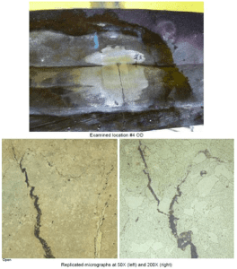
of 50x (bottom left) and 200x (bottom right) showing crack propagation in intergranular manner.
Improvements
To address the recurrence issues, several critical improvements were implemented in the fabrication process of the new unit of Boiler Feed Water Preheater. These improvements were implemented to enhance the structural integrity, welding quality, and long-term reliability of the equipment, with a particular focus on the challenges associated with high-temperature, high-pressure hydrogen service.
The improvements began with a thorough review of international standards, particularly API RP-934, especially API RP 934-A for pressure vessels made of 2-1/4 Chrome-1 Molybdenum Steel, and API 941 for materials in hydrogen service. Based on these guidelines, a meticulous and comprehensive approach was adopted, addressing key technical aspects such as material and consumable testing, welding techniques, heat treatment methods, and advanced inspection procedures.
One significant improvement was the elimination of local PWHT. Instead, furnace PWHT was mandated for all weldments. Thermocouples were placed on both the internal and external surfaces to ensure uniform temperature distribution and effective stress relief and restoring toughness throughout the weldment and heat affected zone (HAZ), as shown in Figure 6 below. This method mitigates the high hardness and residual stress that can lead to crack formation and growth.
As for welding procedure, it was mandated that Intermediate Stress Relief (ISR) be used instead of allowing the alternative Dehydrogenation Heat Treatment (DHT), even though DHT in lieu of ISR can be considered for non-restrained joints of conventional or advanced low alloy steel grades, and is commonly allowed for conventional steels on non-restrained welds, as per API RP-934-A. Although a DHT will reduce hydrogen, it will not sufficiently restore toughness, as would an ISR, especially for advanced materials which remain very brittle during pre-PWHT handling. Due to the repetitive crack incidents, even though the material of E-02A/B/C is of only conventional steel grades and the affected joints are not considered as restrained, the authors deemed the ISR would be really contributing and therefore had specified it as a compulsory requirement.
The inspection methods were also significantly upgraded to enhance defect detection in the circumferential welds. While methods like radiography and colour contrast dye penetrant testing (DPT) would normally be effective, their limitations in detecting subtle defects in low alloy steels prompted the inclusion of PAUT, and fluorescent penetrant test. PAUT provides high-resolution, real-time imaging, enabling the detection of cracks with greater sensitivity.
This method ensures that even small defects are identified during fabrication, improving the defect-free delivery of the equipment and reliability of the equipment.
In addition to PAUT, hardness testing was emphasised pre- and post-heat treatment, to validate material strength and toughness, ensure compliance with specifications, and detect any defects or anomalies that might have resulted from improper heat treatment as shown in Figure 7. Replica testing was also introduced to detect any microscopic and metallurgical issues that visual inspection might have missed, ensuring comprehensive weld quality evaluation.
These improvements—ranging from enhanced material and consumable requirements, and advanced welding techniques to state-of-the-art inspection methods—are all aimed at improving the long-term reliability and operational safety of the equipment. By doing rigorous root cause analysis and adhering to its findings, API 934 guidelines, integrating industry best practices, these changes ensured that the equipment can reliably perform under demanding operating conditions, minimising risks of failure and maximising operational efficiency.

Moving forward
treatment.
While several fabrication and inspection improvements have been made to the new units, the possibility of cracks still developing at the weldments in the near or far future of service persists. Therefore, a suitable replacement strategy and permanent resolution must be further developed. This will include proposing a fail-proof design improvement, along with properly engineered heat treatment protocols that can reduce material susceptibility to cracking while enduring the severe high-temperature, high-pressure hydrogen service conditions.
Looking ahead, the next step would involve leveraging on advanced Finite Element Analysis (FEA) and Computational Fluid Dynamics (CFD) simulations to further investigate any potential design shortcomings and refine it based on findings from a detailed thermo-mechanical stress analysis. These advanced simulations will enable a deeper understanding of how the equipment responds under actual operating conditions, transient or steady state, highlighting any areas that could benefit from incremental improvements.
Moreover, continuous improvement remains a key focus, aiming not only to address current issues but also to eliminate their root causes permanently. Through ongoing optimisation of design, materials and consumables selection, fabrication processes, and inspection protocols, it will be possible to achieve a higher standard of equipment integrity and reliability.
Conclusion
In conclusion, the comprehensive approach taken in addressing the issues related to the Boiler Feed Water Preheater Heat Exchanger has successfully incorporated some fabrication improvements, focusing on enhancing material testing, welding practices, heat treatment processes, and inspection methodologies. These actions were driven by a commitment to resolving the root causes of previous failures and improving the long-term reliability of the equipment in high-temperature, high-pressure hydrogen service. The implementation of post weld heat treatment (PWHT) of the whole equipment inside a furnace, making obligatory the Intermediate Stress Relief (ISR) instead of Dehydrogenation Heat Treatment (DHT), and the adoption of advanced inspection techniques such as Phased Array Ultrasonic Testing (PAUT), etc. all served to significantly improve the structural integrity and operational safety of the equipment. The commitment to continuous improvement ensures that the equipment will perform at its highest potential, minimising risks, and enhancing plant operational performance for years to come.
References:
- American Petroleum Institute. (2008). API 934-A: materials and Fabrication of 2-1/4Cr-1mo Steel Heavy Wall Pressure Vessels for High-Pressure Hydrogen Service Operating at Temperatures Above 825°F (440°C). Washington, DC: American Petroleum Institute.
- American Petroleum Institute. (2020). API 941: Steels for Hydrogen Service at Elevated Temperatures and Pressures in Petroleum Refineries and Petrochemical Plants (Nelson Curve) (8th ed.). Washington, DC: American Petroleum Institute.
- American Society of mechanical Engineers. (2021). ASmE boiler and Pressure Vessel Code, Section VIII, Division 2: Alternative Rules – Pressure Vessels. New York, NY: ASmE.
- Tubular Exchanger manufacturers Association. (2019). TEmA Standards: Standards of the Tubular Exchanger manufacturers Association (10th ed.). Tarrytown, NY: TEmA.
- Firth, D. m., Keen, D., Jones, C., & Karstensen, A. (2005). Cracking and repair of closing welds in 2.25 Cr-1 mo steel vessels operating in high temperature synthesis gas. In Ammonia Technical manual (Vol. 2005). mPT Solutions, PO box 31-310, Lower Hutt, New Zealand.
About the authors
 Ir. Ts. Nur Athirah bt Ishar is a Staff Engineer with 13 years of experience in mechanical static equipment within the ammonia-urea fertiliser industry. Starting her career in maintenance, she managed reliability programmes and major repairs of pressure vessels, tanks, and heat exchangers. Now a Technical Authority at PETRONAS plant, she leads solutions for static equipment integrity and compliance. She holds a mechanical engineering degree and Graduate Certificate from Stevens Institute of Technology, NJ. A passionate advocate for continuous improvement, she actively contributes to training, seminars, and technical publications. Outside of work, she enjoys reading, gardening, and traveling.

Ir. mohd. Norhisyam Awang is a Principal mechanical Engineer with 28 years of experience in the petrochemical industry holding engineering roles at PETRONAS plants including manager, Reliability, Project and maintenance Engineer. He specialises in static unfired equipment but also has exposure to rotating, fired, and bulk handling systems. He holds a bachelor of Science in mechanical Engineering & Applied mechanics from university of Pennsylvania, Philadelphia, uSA, master of business Administration (muamalah) from Selangor Islamic university and a Grade 1 Steam Engineer certification. Currently serving as Principal Static unfired in PETRONAS, he provides vital consultations and solutions for mechanical static issues, leading improvements and establishing best practices for plant equipment, work processes, and technical standards. Off-duty, he enjoys off-roading, scuba diving, and camping.
About this Technical Story
This Technical Story was first published in Heat Exchanger World Magazine in October 2025. To read more Technical Stories and many other articles, subscribe to our print magazine.
Technical Stories are regularly shared with our Heat Exchanger World community. Join us and share your own Technical Story on Heat Exchanger World online and in print.