In Part 1 of this comprehensive guide, we explored the initial steps of the design workflow. Now, in Part 2, we will continue our journey, diving into the remaining steps, including flow and pressure drop analysis, detailed design and drawings, fabrication and quality assurance, and installation and commissioning.
By Muhammad Rehan – Mechanical Engineer
In the previous article, we started by defining the requirements and specifications, understanding the purpose and performance goals of the heat exchanger. Then, we moved on to the preliminary design phase, where we determined the heat exchanger type, number of tubes, and shell dimensions.
We then delved into the thermal design phase, calculating the heat duty and surface area requirements. Finally, we covered the mechanical design phase, considering factors such as tube layout, structural integrity, and material selection. By the end of this guide, you will have a comprehensive understanding of the entire design and fabrication process, equipping you with the knowledge and tools to create efficient and reliable shell and tube heat exchangers.
Flow and pressure drop analysis
Flow and pressure drop analysis is a key step in the design of a shell and tube heat exchanger. It involves studying the fluid flow patterns and calculating the pressure drop experienced by the fluids as they pass through the heat exchanger. This analysis helps optimize the design to ensure efficient heat transfer and minimal pressure losses.
During the flow and pressure drop analysis, the following activities are typically performed:
- Fluid flow patterns: The analysis examines the flow distribution within the heat exchanger to ensure uniform fluid distribution across the tubes. It considers factors such as the number of tube passes, baffle design, and tube layout to achieve balanced flow patterns and avoid bypassing or maldistribution of the fluids.
- Pressure drop calculations: Pressure drop refers to the decrease in fluid pressure as it flows through the heat exchanger. The analysis involves calculating the pressure losses in various components, including tubes, baffles, headers, and connections. Accurate pressure drops calculations help determine the pumping power required and ensure that pressure limits are within acceptable ranges.
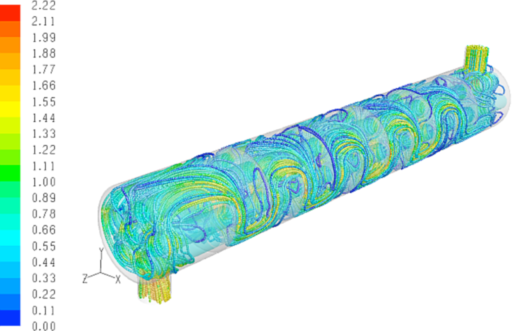
- Optimised flow distribution: The goal is to minimize pressure drops while maintaining effective heat transfer. The analysis may involve adjusting the baffle spacing, tube diameter, or other design parameters to optimize the flow distribution and reduce pressure losses. Computational fluid dynamics (CFD) simulations or empirical correlations are often used to evaluate distinctive design configurations.
- Fluid velocity profiles: The analysis examines the velocity profiles of the fluids within the heat exchanger. Understanding the velocity distribution helps ensure proper fluid mixing, adequate turbulence for enhanced heat transfer, and avoidance of dead zones where fouling or heat transfer limitations may occur.
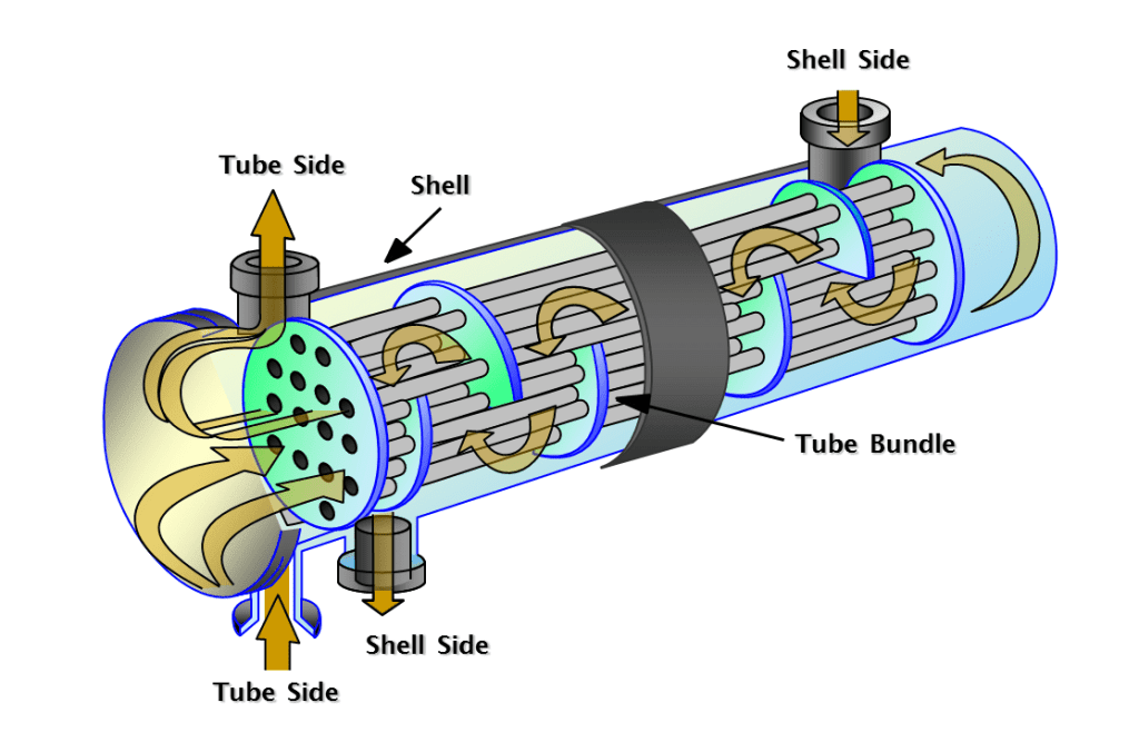
Figure 1 – Shell and Tube Heat Exchanger
Several software tools can be utilized for flow and pressure drop analysis of shell and tube heat exchangers. Some commonly used software includes:
- ANSYS Fluent: A widely used computational fluid dynamics (CFD) software that can simulate fluid flow and heat transfer phenomena in complex geometries.
- COMSOL Multiphysics: Multiphysics simulation software that offers capabilities for fluid flow analysis and heat transfer simulations.
- Aspen Plus: A process simulation software that can model and analyse fluid flow, including pressure drop calculations and heat transfer performance.
- HTRI Xchanger Suite: A specialized software suite specifically designed for the design and analysis of heat exchangers, including flow distribution and pressure drop calculations.
These software tools provide advanced modelling and simulation capabilities to analyse flow patterns, pressure drop, and heat transfer characteristics of shell and tube heat exchangers. They help engineers optimise the design, predict performance, and ensure efficient operation of the heat exchanger. The specific software chosen depends on factors such as project requirements, available resources, and organizational preferences.
The deliverables of the flow and pressure drop analysis step in the design of a shell and tube heat exchanger typically include:
Analysis report: A comprehensive report summarizing the findings and results of the flow and pressure drop analysis. This report may include the following information:
- Description of the flow distribution patterns and velocity profiles within the heat exchanger.
- Calculation and documentation of pressure drop values for different components, such as tubes, baffles, headers, and connections.
- Evaluation of the pressure losses and their impact on the overall performance of the heat exchanger.
- Optimization recommendations to minimize pressure drop while ensuring effective heat transfer.
- Discussion of any limitations or assumptions made during the analysis.
Design modifications: If necessary, the flow and pressure drop analysis may lead to design modifications to improve the performance of the heat exchanger. These modifications could include adjustments to the baffle spacing, tube diameter, tube layout, or other relevant design parameters. The specific details of the design modifications should be documented and communicated as part of the deliverables.
Documentation of software used: If software tools such as ANSYS Fluent, COMSOL Multiphysics, Aspen Plus, or HTRI Xchanger Suite were utilized for the analysis, the deliverables may include documentation of the software used, including versions, input fi les, and setup details. This documentation ensures transparency and reproducibility of the analysis. The analysis report and associated deliverables serve as important documentation for the design process. They provide valuable insights into the flow behaviour, pressure drop characteristics, and optimization recommendations for the shell and tube heat exchanger. These deliverables can be used as references for design reviews, project documentation, and communication with stakeholders involved in the heat exchanger design and fabrication process.
Detailed design and drawings
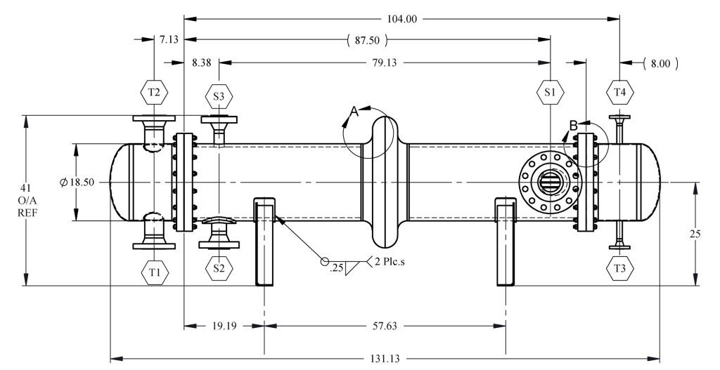
The manufacturing drawings for the shell and tube heat exchanger are typically prepared by a team of professionals, including mechanical designers, drafters, and engineers. The specific responsibilities and roles may vary depending on the organization and project structure.
In most cases, mechanical designers or design engineers are primarily responsible for creating the manufacturing drawings. They work closely with drafters or CAD (Computer Aided Design) technicians who assist in translating the design specifications into detailed engineering drawings using computer-aided design (CAD) software.
The process may involve the following steps:
- Mechanical design: The mechanical designer or design engineer develops the detailed mechanical design of the heat exchanger, considering factors such as tube layout, baffle design, structural components, material selection, and welding requirements.
- Drafting and CAD: The drafters or CAD technicians use the specifications provided by the mechanical designer to create the manufacturing drawings. They utilize CAD software to accurately depict the components, dimensions, tolerances, and assembly details of the heat exchanger.
- Collaboration and review: The mechanical designer reviews the manufacturing drawings to ensure they align with the design specifications. Any necessary modifications or corrections are communicated to the drafters, who make the appropriate revisions.
- Quality assurance: The manufacturing drawings undergo quality assurance checks to verify compliance with design requirements, accuracy, and completeness. This may involve internal reviews, interdisciplinary coordination, and adherence to relevant industry standards and codes.
It is important to note that the specific workflow and responsibilities may vary across organizations. Larger projects or companies may have dedicated drafting teams or separate manufacturing engineering departments involved in the creation of manufacturing drawings. The manufacturing drawings are a collaborative effort between the mechanical design team and the drafters or CAD technicians, ensuring the accurate representation of the heat exchanger design for fabrication and construction purposes.
Fabrication and quality assurance
This step involves the actual manufacturing of the heat exchanger according to the design specifications and ensuring that it meets the required quality standards. Here is a brief explanation of this step:
Fabrication process:
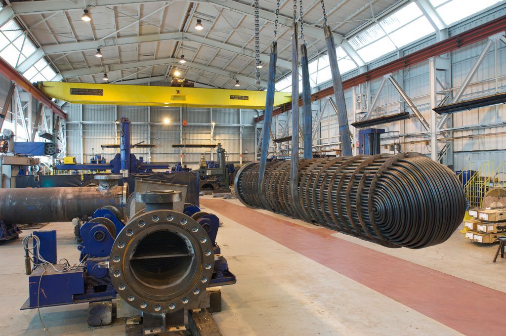
- Fabrication of the heat exchanger components: This includes cutting, forming, welding, and assembling the various parts of the heat exchanger, such as the shell, tubes, tube sheets, baffles, headers, and supports.
- Material selection and preparation: The appropriate materials specified in the design phase are procured and prepared for fabrication, ensuring they meet the necessary quality and dimensional requirements.
- Welding and joining: Skilled welders perform the welding operations according to approved procedures, ensuring proper penetration, integrity, and structural strength of the joints.
- Assembly and integration: The fabricated components are assembled, including attaching the tubes to the tube sheets, installing baffles, headers, and other necessary elements, and ensuring proper alignment and fit.
Quality Assurance:
- Inspection and testing: Various quality checks and inspections are carried out during the fabrication process to verify compliance with design specifications and industry standards. This includes visual inspections, dimensional checks, and non-destructive testing (NDT) methods such as ultrasonic testing, radiography, or dye penetrant testing to identify any defects or imperfections.
- Pressure testing: The completed heat exchanger undergoes pressure tests to ensure its integrity and ability to withstand the required operating conditions. This typically involves subjecting the heat exchanger to a specified pressure and monitoring for any leaks or
failures. - Documentation and traceability: Detailed records of inspections, tests, and procedures are maintained, providing traceability and documentation of the fabrication process. This documentation helps ensure accountability, facilitates future maintenance and troubleshooting, and demonstrates compliance with applicable standards or codes.
- Compliance with regulations and standards: The fabrication process adheres to relevant industry codes, standards, and regulatory requirements to ensure the heat exchanger meets safety, performance, and quality criteria.
The deliverables of the fabrication and quality assurance step include:
- Fabricated heat exchanger: The completed and fully assembled heat exchanger, ready for installation.
- Inspection and test reports: Documentation of inspections, NDT results, and pressure test reports, providing evidence of compliance with design requirements and quality standards.
- Material certificates: Documentation certifying the quality and properties of the materials used in the fabrication process.
- Welding documentation: Records of the welding procedures, qualifications of welders, and any required welder certifications.
- Compliance documentation: Documentation demonstrating compliance with relevant codes, standards, and regulations.
The fabrication and quality assurance step ensures that the heat exchanger is manufactured to the required specifications, meets quality standards, and is ready for installation and operation.
Installation and commissioning
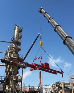
The “installation and commissioning” phase is the last step in the development of a shell and tube heat exchanger. It involves the proper installation of the heat exchanger in its intended location and the subsequent commissioning to ensure its functionality and performance. Here is a brief
explanation of this step:
Installation:
- Site preparation: The installation site is prepared by ensuring proper space availability, suitable foundation or support structures, and necessary utilities such as piping connections, electrical supply, and instrumentation.
- Rigging and transportation: The heat exchanger, which is typically a large and heavy piece of equipment, is carefully rigged, lifted, and transported to the installation site using appropriate lifting and transportation equipment.
- Alignment and leveling: The heat exchanger is aligned and leveled to ensure proper integration with the surrounding equipment and to maintain its structural integrity.
- Piping and connections: The necessary piping connections, valves, and fittings are installed to facilitate the flow of fluids into and out of the heat exchanger.
- Instrumentation and controls: Any required instrumentation, sensors, and control systems are installed to monitor and control the performance of the heat exchanger.
Commissioning:
- Start-up procedures: The heat exchanger is gradually brought into operation, following established start-up procedures. This involves checking and verifying the proper functioning of valves, pumps, instruments, and control systems.
- Performance testing: Performance tests are conducted to evaluate the heat exchanger’s efficiency, heat transfer effectiveness, and overall performance. This may involve measuring temperature differentials, flow rates, pressure differentials, and other relevant parameters to ensure that the heat exchanger operates within the specified design parameters.
- Adjustments and fine-tuning: If any discrepancies or issues are identified during the commissioning process, adjustments and fi ne-tuning are made to optimize the heat exchanger’s performance. This may include modifying flow rates, adjusting control parameters, or making minor design changes, if necessary.
- Documentation: Comprehensive documentation is prepared, including commissioning reports, test results, and operating procedures. This documentation serves as a reference for future maintenance, troubleshooting, and operation of the heat exchanger.
The deliverables of the installation and commissioning phase include:
- Installed and operational heat exchanger: The heat exchanger is successfully installed, connected, and ready for operation.
- Commissioning reports: Documentation of the commissioning process, including start-up procedures, performance tests, adjustments made, and test results.
- Operating procedures: Detailed instructions and guidelines for the proper operation and maintenance of the heat exchanger.
- Handover documentation: Final documentation, including any as-built drawings, equipment manuals, and warranties, handed over to the owner or operator of the heat exchanger.
The installation and commissioning phase ensures that the heat exchanger is correctly installed, integrated with the system, and performs as intended. It marks the completion of the project, with the heat exchanger ready to fulfil its role in facilitating efficient heat transfer in the process or system it is designed for.
Conclusion
In summary, I have tried to summarize a practical guide to design and fabricate shell and tube heat exchangers. Note that this guide is only a brief reference guide for beginners to understand the workflow. Designing heat exchangers requires in-depth knowledge and understanding of fluid dynamics, thermodynamics, engineering mechanics and mechanics of materials.
About the author
 Muhammad Rehan is a Mechanical Engineer in the petrochemical industry. He has twelve years of experience in engineering, reliability, construction, commissioning and inspection management of pressure equipment, piping systems, fired heaters, and heat exchangers.

