
Tube-to-tube heat exchangers are critical for plant operations, current inspection methods primarily focus on surface checks, overlooking internal defects that could compromise safety and production. To address this gap, FORCE Technology has developed an automated ultrasonic solution capable of efficiently detecting embedded defects within welds and providing detailed documentation.
By Jens Peter Bertelsen, Project Manager at FORCE Technology

Heat exchangers are critical components in many chemical processing plants. Their safe and reliable operation is an important issue for the operators. Currently, inspection of the tube-to-tube sheet welds in the heat exchangers is normally limited to various methods for surface inspection, while defects inside the welds remain undiscovered, which could compromise safety and could lead to failure and production stops. To overcome this issue, FORCE Technology has developed an automated ultrasonic solution, which is capable of finding small, embedded defects in the welds, is time efficient and provides detailed documentation of the inspected welds. This paper describes the company’s solution and how we apply it.
Introduction
Inspection of tube-to-tube sheet welds are traditionally limited to visual, liquid penetrant and hydrogen leak testing. All these techniques only provide information about the surface condition of the inspected welds, such as surface cracks or other surface breaking discontinuities. The mentioned inspection techniques are not able to detect any internal weld defects such as lack of fusion or cluster porosity. Internal defects are crucial for weld integrity. FORCE Technology has developed an alternative technique based on standard ultrasonic examination principles, which can detect them.
The technique offers a lot of benefits for their customers and significantly increases the level of confidence they have in the examined heat exchangers. The technique is very fast, thus minimising downtime and provides full scanning of the welded volume. Therefore, defects such as lack of fusion, inclusions or clustered porosity are easily detectable. The technique makes it possible to save detailed data for each particular weld, including precise dimensioning and positioning of detected defects inside the weld. The data can either be used for on-site reporting or, if needed, at a later stage. The equipment is easily transportable and does not require any safety preparations prior to testing, except for those required by the customer.
Ultrasonic NDT technique
The technique is making use of normal ultrasonic testing principles but is applied with a specially designed scanner. It can scan the weld for internal indications in the full weld length, a 100% circumferential area and to size eventual indications. Internal indications such as lack of fusion, cluster porosity, inclusions and cracks are easily detectable. The ultrasonic probe is positioned in the scanner’s hollow shaft and inserted into the inspected tube in the heat exchanger. The probe is rotated and translated axially simultaneously, thus performing a screw spiral movement. Inspection starts and stops a couple of millimetres before and after the weld, respectively. A centring mechanism is keeping the inspection head centred in the tube. The specially designed scanner enables fast and accurate inspection of the weld. Inspection rate is between 60 and 90 welds per hour. Below the weld inspection principle is illustrated.
Automated data collection
Data collection is based on FORCE Technology’s automated ultrasonic inspection system, called P-scan. The system was first developed by the company in the 1970s and has since been under constant development and improvement. The system can be applied in many areas and its further development is based on regular use and accumulated field experience. Furthermore, we have developed a wide range of scanners, based on the P-scan system, adaptable to specific applications within different industries. Essentially, the P-scan is a computer-based ultrasonic inspection system for automated, mechanical, or manual inspection of structures, welds and assembly of components. The P-scan system has documentation and storage facilities for all data related to each inspection operation and include visualisations of the inspection results in the form of high-quality images of the material volume examined.
The P-scan system can provide different kinds of information. It has an A-scan, B-scan, C-scan, T-scan (thickness measurement) and TOFD (time-of-flight diffraction) mode. Furthermore, the system provides projection images of the object under examination. With the three projection images, called Top View, Side View and End View, any imperfection which have been detected are automatically shown at their correct 3D location. The system’s excellent traceability and documentation possibilities is very valuable for the operator and owner.


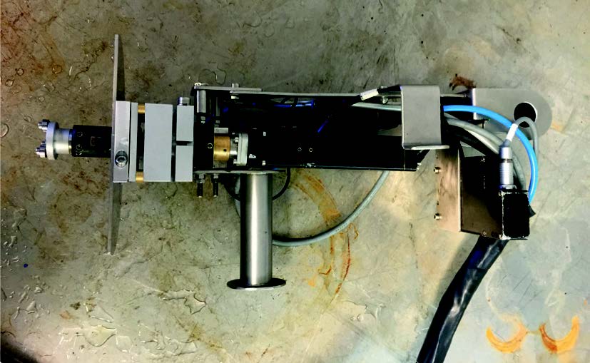
The tube-to-tube sheet scanner
FORCE Technology tube-to-tube sheet scanner, named AHS-1, is a handheld unit, which either can be operated by the scanner operator or remotely from a laptop. The scanner basically consists of a motor, a shaft with an ultrasonic transducer and a keypad for local scanner control. A centring mechanism is positioned at the end of the shaft, just in front of the ultrasonic probe. The shaft is hollow and contains cables for the transducer and a hose for water supply, as water is used as coolant between transducer and inner tube wall. The motor rotates and translates the shaft together with the transducer.
The scanner can be equipped with different probes, depending on the expected type of defect. Zero-degree probes are typically used for detection of lack of fusion or cluster porosity, while angled probes are used for detection of cracks in the welds. Inspection rate depends largely on the inner diameter of the inspected tube and is larger for small diameters and lower for large diameters. One-inch tubes are typically scanned with one rotation per second, i.e. a weld with a leg length of 5mm is being scanned in approximately 10 seconds. The scanner is calibrated so that the position of the artificial defects in the mock-up is well defined, enabling positioning and sizing of potential defects in the actual heat exchanger welds.
Calibration of the system
Prior to inspection, the system has to be calibrated on a mock-up. The mock-up consists of 3-5 tubes in a tube sheet of identical design, as the heat exchanger that is to be examined. Full geometrical identity of diameters, thicknesses, positions and welding parameters should be ensured. Artificial defects are introduced in the mock-up welds, however, one of the welds must be kept without any welding defects. Depending on the requirements, the artificial defects can be side drilled flat bottom holes or lack of fusion defects prepared during welding of the tube in the mock-up. As the scanner needs to be prepared to fit the actual tube geometry, the mock-up must be sent to us in sufficient time before the actual testing.
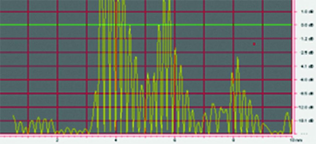
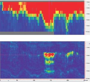
The screenshot on this page shows a scanning with two lacks of fusion defects.
The screenshot is shown in A, C and D scan. The scan is from a tube with dimensions
57.0 x 4.0mm. Defect 1 has a 30deg. circumferential extent, corresponding to 12.8mm circumferential length with amplitude 11dB above ref. 0dB and defect 2 has a 5deg. circumferential extent, corresponding to 2.1mm circumferential length with amplitude 2dB above ref. 0dB. The red colour from 0-4mm in C-scan image, is signals from the tube back wall, recorded prior to the UT transducer enter the weld area. The weld-root area starts at the yellow horizontal line. From the D-scan we see defect no. 1 has maximum amplitude at approx. 4mm’s depth, which is in the weld root area.
Fast-rate inspection
The technique has good versatility and adaptability to various tube dimensions, from 12mm in internal diameter. It finds various types of weld defects and weld leg-length can be determined as well. Maximum scanning length is up to 80mm in standard scanner setup. An important requirement is that the inner surface of the tubes must be clean, free of scale, corrosion or other impurities. As the equipment needs both power and water supply, normal safety and security measures for such cases apply, but no additional measures are required during inspection. The equipment is easily portable, which makes it easy to reach customers anywhere in the world. During a 12-hour shift, around 500-600 welds are examined and a preliminary report stating any severe findings will be issued prior to the inspection team leaving from the site. Such high inspection rate significantly reduces downtime of the system and, combined with the high quality of data and documentation, provide a clear advantage over the more traditional inspection methods.
Conclusions
FORCE Technology’s tube-to-tube sheet weld scanner provides fast and accurate detailed data on the condition of the welds in the inspected tube sheet and thus represents a better solution than alternative traditional inspection techniques. The technique has been successfully applied for tube-to-tube sheet weld inspection on a number of projects worldwide. For years, FORCE Technology has been on the front edge of innovation in many fields, including NDT education and inspection. Our tube-to-tube sheet weld scanner is a prove of that.
About the author

Jens Peter Bertelsen have been working at FORCE Technology for 20 years and is responsible for inquiries concerning Eddy Current-, Iris-, Long Range- and Tube-to-Tube sheet (TTS )weld inspections and do often make the inspections at sites.
About this Technical Story
This Technical Story was first published in Heat Exchanger World Magazine in June 2024. To read more Technical Stories and many other articles, subscribe to our print magazine.
Technical Stories are regularly shared with our Heat Exchanger World community. Join us and share your own Technical Story on Heat Exchanger World online and in print.