
As the world intensifies its efforts to combat climate change, carbon capture and storage (CCS) technologies have become crucial in reducing greenhouse gas emissions. This article delves into the heat transfer challenges associated with three prominent CCS methods: amine-based absorption, cryogenic carbon capture, and direct air capture and Kelvion’s heat exchange solutions. Each of these methods presents unique engineering hurdles that must be overcome to enhance their efficiency and effectiveness. By exploring the latest advancements and solutions in heat exchanger technology, we aim to shed light on how these challenges are being addressed, paving the way for more sustainable and scalable carbon capture solutions.
By Roy Niekerk, Global Director Application Engineering, Kelvion
Post-combustion
The amine wash process is one of the most established and commercially available carbon capture technologies, widely used in industries.
Several companies and research institutes offer amine-based carbon capture solutions, for example:
- Mitsubishi Heavy Industries, ‘KM CDR’ process
- Aker Solutions, Aker CO2 capture process
- Shell, Cansolv CO2 capture technology
- Fluor, Econamine FG+™ process
Most amine-based carbon capture technologies follow similar underlying principles of chemical absorption, though the solvents although proprietary names might vary (e.g., MEA, DEA, proprietary blends). They all rely on the same core concept of using amines to absorb CO2 from gas streams.
All absorption-based carbon capture systems, including those using amines, require multiple heat exchangers for the regeneration of the solvent, energy optimisation, and maintaining system efficiency. The captured CO2 must be desorbed from the solvent using heat, which necessitates an efficient heat exchange process.

Flue gas heat recovery
When amine systems are used after a gas or coal fired power plant, the flue gas must first be cooled before it can enter the amine system. Because of Henry’s Law, absorption of gases into a liquid works better at lower temperatures. And amine solutions would degrade if temperatures get too high, which leads to fouling and corrosion in the amine system. The flue gas should typically enter the absorption column at 40°C to 60°C (104°F to 140°F)[1].
The flue gas coming from a normal coal or gas fired power plant is at close to atmospheric pressure. One heat exchanger type that can be used here is tube bundles in rectangular flue gas duct as can be seen in Figure 1 below. There is a lot of freedom in the type of tube used. These can be any diameter, pitch and material suitable for the process. For instance, when it is expected that the cooling of the flue gas passes through the acid dew point, high allow materials can be applied to avoid corrosion issues. A technology that offers maximum efficiency is Kelvion’s Rekuluvo / Rekugavo, which is a welded plate type. This is a perfect solution for exchanging heat between two ‘close-to-atmospheric’ gases. The construction provides a countercurrent flow which enables close temperature approaches and high thermal efficiencies. Compared with other technologies, such as the tubular type described above, it is much more compact and lighter weight. However, both types are sufficiently accessible for cleaning.


Air-cooled heat exchangers using Groovy and Diesta
In both the regenerator column condenser and in the lean amine cooler, large amounts of heat must be dissipated. An often selected heat exchanger type in these positions is the air cooled heat exchanger (ACHE). The outside of the tube is provided with thin aluminum fins to enlarge the area which is in contact with the ambient air as much as possible. Although the air is moved through the tube bundle by the use of big electrical motor drive fans, the heat transfer coefficient on the air-side remains low.
To improve the heat transfer coefficient on the air-side, Kelvion introduced the Groovy fin (see picture 4), almost two decades ago. Instead of normal flat fins, the fin is provided with three waves, or ‘grooves’. When the air passes the tube, the groove causes the air to bend a bit behind the tube as well, which significantly improves the heat transfer. Of course, at the same air velocity, this groove gives a slightly higher pressure drop. Therefore, it is fair to make a comparison at equal fan power. And it turns out that at equal fan power, the Groovy Fin provides up to 20% higher heat transfer coefficient. More than 5,000 bundles with Groovy fins have been installed worldwide in various processes.
There can also be a significant heat transfer resistance on the inside of the tube, which happens with fluids that have an elevated viscosity. This is exactly the case in the lean amine cooler, where the viscosity gets even higher because of the cooling. To overcome this, Kelvion introduced the DIESTA tube which an acronym that stands for Double Internally and Externally Structured Tube for Air fin coolers.
For both Groovy Fins and DIESTA, a special HTRI plug-in (dll file) has been developed which can be obtained on request from Kelvion.
It is obvious that when the heat transfer coefficients in the air-cooled heat exchangers get higher, the required heat transfer area will be lower. Hence, a smaller heat exchanger can be used. In fact, selecting Groovy or DIESTA will lead to a 10-20% smaller installation which reduces costs in the foundation, steel structure and installation plot.


Regeneration reboiler
When licensors are marketing their amine technology, they often mention the energy per tonne of captured CO2. Most of this heat is used inside the regenerator reboiler. As an average number, 2.3 GJ per tonne CO2 is used as heat in the reboiler[2]. Using this number, a project that aims to capture 8 MTPA of CO2 requires a reboiler of 580 MW.
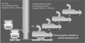
The common heat exchanger type for reboilers in industry is the shell & tube (S&THE). And in amine systems the kettle type S&THE is often seen. It is reliable, well known and can work at almost 0% turndown ratio. However, it is also heavy and big. When developing large-scale CCS projects, project developers face several challenges. First of all, the number of reboilers that need to be put around the column gets too big to be practical. When more than four units are needed, the space around the column gets congested and the vapour return piping gets very complex. Secondly, more and more project developers are seeking modularisation of their systems. This requires more compact and lower weight heat exchangers.
Welded plate heat exchangers can offer great benefits in use as amine reboilers. Kelvion’s K°FLEX is such a welded plate heat exchanger. In one study case, four heavy kettle type reboilers with a weight of 89 tonnes and a footprint of 6,900 x 11,400 mm could be replaced by two K°Flex thermosyphon reboilers with a weight of 58 tonnes and a footprint of 3,870 x 7,060 mm.
A welded plate heat exchanger will also result in less solvent degradation and hence less system fouling and corrosion. Also, a welded plate heat exchanger works at lower wall temperatures on the solvent side and will have a lower residence time.
Carbon capture by desublimation – cryogenic
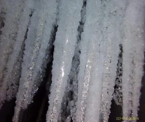
Desublimation is the direct phase change of a gaseous substance into the solid, crystalline phase. This physical phenomenon is known from nature: in winter air-bound moisture is deposited as white frost.
In the chemical industry, desublimation is used to separate chemical components from a gas stream. Kelvion has been supplying switch condensers for the production of phthalic anhydride (PA) since the 1950s. It is called switch condenser because of the batch operation nature, where in a first step you cool desublimator and collect crystals. When the unit is completely loaded with crystals, you ‘switch’ to the recovery mode, where you heat up the unit end melt off the collected component. Several parallel units are used for a semi-continuous operation.
Desublimation has been used in many different processes such as cleaning tank venting from naphthalene and the protection of vacuum systems.
More than a decade ago, Kelvion started to investigate the removal of CO2 by means of desublimation. The first challenge to overcome was the fact that there were no solid-gas equilibria available in the literature. Mathematical equilibrium models were developed in collaboration with the Ruhr University Bochum (RUB) at the Department of Fluid Process Engineering with Prof. Grünewald. There have been several master theses using this model predicting separation of CO2 in solid form in binary and multicomponent mixtures with methane, pentane, butane, etc. Of course the question then is: how accurate is such a mathematical model?

Verification of the models was done through experiments at CSIRO in its cryogenic lab in Melbourne, Australia. Important results were achieved in this experiment. First of all, it gave a visualisation of the formation of CO2 crystals which proved the CO2 separation concept and gave insight into the morphology of the crystals. Secondly, it was measured that a gas stream containing 20% CO2 at the inlet only contained 0.5% CO2 at the outlet. Thirdly, the mathematical model developed by RUB was verified and found to be accurate. The obtained results were the basis to investigate the practical application of desublimation as a carbon capture method. One such application was found in bio-LNG production. Biofrigas with its headquarters in Göteborg, Sweden, offers small scale, container based, liquefaction plants for bio-LNG production from biogas or biomethane. When biogas comes out of the digestors, it contains too much CO2 to put directly into LNG. Kelvion supplied desublimators for a full-scale pilot project, which was very succesful.
Obtained results:
- Concentration of CO2 in the specified range of bio-LNG
- Cycle times confirmed for continuous operation
- Morphology of crystals confirmed desublimator process design
- Required CO2 capturing capacity of desublimators confirmed
Direct air capture
![Figure 9: Process diagram direct air capture [3].](https://b1982122.smushcdn.com/1982122/wp-content/uploads/sites/19/2025/06/Figure-9-300x127.jpg?lossy=1&strip=1&webp=1)
In a liquid-based system, the air is brought into contact with a liquid that contains a chemical solution and removes the CO2 from the air. In another step of the process, the liquid must be regenerated and the CO2 released for further processing and which can then be stored underground for instance in geological formations. Big amounts of air are being processed, and these will be large-scale installations.
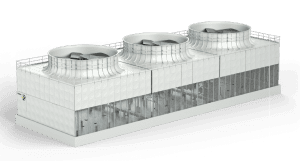
The principle of the ‘air contactor’ or ‘contact tower’, in which a large contact area between air and a liquid must be provided, shows many similarities to a well-established technology in industry: the cooling tower. In both a cooling tower and a contact tower, the fluid is divided and sprayed from the top over a polymeric fill structure. The polymeric fill enlarges the contact area and contact time with air. The air is sucked through the fill by using a large fan which is installed in a fan hood on the top of the tower. Different fill structures can be provided. The finer the structure, the higher the efficiency. However, a finer structure is also more sensitive to fouling because of dust and particles from the air, or, in the case of DAC, precipitation material. An optimisation must be made.
An important aspect that distinguishes the Kelvion Polacel cooling tower from other types is the stainless steel, bolted construction. It enables ultra-fast onsite erection or even offsite pre-assembly in complete cells, or building blocks which are then hoisted easily on the basins to minimise site work.
Conclusion
The journey towards effective carbon capture and storage (CCS) is marked by significant technological advancements and engineering challenges, particularly in the realm of heat transfer. This article has explored three prominent CCS methods: amine-based absorption, cryogenic carbon capture, and direct air capture, each presenting unique heat exchanger challenges.
Amine-based absorption, a well-established method, relies heavily on efficient heat exchangers for solvent regeneration and energy optimisation. Innovations such as the Groovy fin and DIESTA tube have significantly improved heat transfer efficiency, reducing the size and cost of installations.
Cryogenic carbon capture through desublimation offers a novel approach, with successful pilot projects demonstrating its potential. The development of accurate mathematical models and practical applications, such as in bio-LNG production, highlight the method’s viability. Direct air capture (DAC) technologies, both liquid and solid-based, require large-scale installations with optimised heat transfer systems. The similarities to cooling tower technology and the use of advanced materials and designs underscore the importance of efficient heat exchangers in these systems.
As the demand for scalable and sustainable CCS solutions grows, continuous innovation in heat exchanger technology will be crucial. By addressing the heat transfer challenges inherent in these methods, we can enhance the efficiency and effectiveness of carbon capture, contributing to a more sustainable future.
 About the author
 About the author
Roy Niekerk has more than 22 years of experience in heat exchangers, both in suppliers as well as in an oil & gas major. He is now VP Hydrogen & New Energies within Kelvion.
References
-
- “Power 101: Flue Gas Heat Recovery in Power Plants, Part I” POWER Magazine, 1 April 2010. [Online]. Available: https://www.powermag.com/power-101-flue-gas-heat-recovery-in-power-plants-part-i.
- N. Mirza en D. Kearns, “State of the art: CCS Technologies 2022,” Global CCS Institute, 2022.
- D. Hospital-Benito, C. Moya, M. Gazzani and J. Paloma, “Direct air capture based on ionic liquids: From molecular design to process assessment,” Chemical Engineering Journal, pp. Volume 468, 2023, 143630, 2023.
About this Technical Story
This Technical Story was first published in Heat Exchanger World Magazine in April 2025. To read more Technical Stories and many other articles, subscribe to our print magazine.
Technical Stories are regularly shared with our Heat Exchanger World community. Join us and share your own Technical Story on Heat Exchanger World online and in print.