
Heliflow is a compact, light and efficient heat exchanger that fits into locations where other heat exchangers have difficulty. The Heliflow can work with pressures up to 1000 barg on the tube side and up to 340 barg on the shell side and withstand 260 degrees Celsius temperature difference between fluids.
This equipment is versatile thanks to its wide range of material options and can therefore suit many application requirements. It is designed for a 100% counter current flow and close temperature approach can be maintained.
Article written in conjunction with Graham’s UK representative: Kinder-Janes Engineers Ltd
The Heliflow heat exchanger encompasses a spiral coil, comprised of multiple parallel tubes mounted within a casing. The case/coil construction creates a spiral fl ow path providing true counterfl ow. Each application is specially engineered for an optimal balance of thermal and hydraulic requirements, resulting in maximum heat transfer effi ciency. High pressure, specialized materials, cyclic operation, temperature extremes and other conditions can be handled without a problem. The Graham Heliflow heat exchanger has years of proven service, in thousands of applications throughout the world.
Coolers or heaters
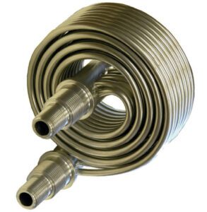
The tubes in the Heliflow are arranged in parallel, starting with an inlet manifold on one end, and terminating at an outlet manifold on the opposite end. The tube bundle is wound into a helical pattern. This coiled construction creates a spiral flow path for the fluid inside the coil.
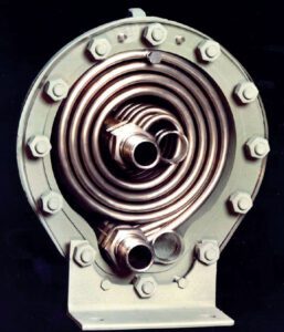
Each tube is in close contact with the tube above and below it. The coiled tube bundle fits into a two-piece casing. When the casing is tightened, it is designed to slightly compress the tubes. Because of the tight fit, the shell side fluid is forced to circulate in a spiral pattern created by the open spaces between the coils.
The seal or process fluid is typically handled on the tube side, while the cooling medium is on the shell side. The tube side can easily be rated for pressures above 70 barg. Standard construction materials include stainless steel for the tube bundle and carbon steel or cast iron for the casing. Copper-nickel and high alloy options, such as duplex stainless steel, are also commonly specified for Heliflow Seal Coolers. Available codes of construction include ASME Section VIII, Div 1, PED and CRN. Heliflow Seal Coolers offer high operating reliability. The effects of fouling are minimized by the turbulent flow and mixing induced by the spiral fluid passages. The casing of the unit can easily be unbolted and removed, which allows for the thorough cleaning of the coolant side without the need to disturb the process piping. The removable casing also allows for quick and easy replacement of the tube bundle, if necessary. The spiral tube bundle eliminates the thermal expansion problems as the bundle is allowed to expand and contract without stressing the tube-to-tube sheet joints.
Possible construction materials:
– Tube side: Copper, stainless steel, admiralty, titanium, cupro-nickel, inconel, duplex stainless steel, monel, steel, other exotic materials.
– Casing material: Cast iron, cast carbon steel, fab-ricated carbon steel, stainless steel, cupro-nickel, hastelloy and other exotic materials.
– Connections: NPT, butt weld, flanged, victaulic, ring joint, others customised.
Heliflow applications:
High pressure applications
The Heliflow heat exchanger is a very efficient choice for heat transfer applications involving high pressure streams on either the tube side, shell side, or both. The unique spiral coil design allows the tube side, which doesn’t rely on gaskets for sealing, to accommodate pressures to 1000 barg without excessive material thickness or difficulty in manufacture. In most high-pressure applications a single process stream is at elevated pressure while the utility stream uses a reduced, nominal pressure fluid. The high-pressure stream is directed to the tube side where, using the application’s required alloy, the coil design will mitigate the use of heavy wall components. In addition, due to the relatively small size and circular shape of the shell, it is possible to custom design units that can accommodate shell side pressures up to 340 barg. The Weld Seal shell design eliminates the gasketed shell joint and reduces the size and weight
of the unit when accommodating a high-pressure shell side stream.
Feed water pre-heaters
This technology can save energy as a heat recovery economiser. Waste heat is recovered and utilized to preheat incoming make-up water that is used in boilers or for other applications.
Industries suitable for Heliflow:
Water heating, water cooling, cryogenic, pharmaceuticals, supercritical CO2 extraction, sanitation, lyophilization, cryogenic, nuclear, LNG production and distribution, CNG delivery, hydrogen, biofuel, chemical and petrochemical.
Liquid to liquid
The equipment offers a good solution for applications that have a liquid-to-liquid service requiring a heat exchanger. When designing the exchanger, the “dirty” fluid should be on the shell side of the unit. Cleaning can be done in-place, without breaking shell side or tube side pipe connections. The flow pattern is 100% counter current that maximizes the temperature differential and thermal efficiency.
Mechanical seal coolers
Keeping the mechanical seal faces cool is extremely important in extending the operating life of mechanical seals.
API flush plans 21 or 23 are the common arrangements for configuring mechanical seal cooling systems. In Plan 21, the product from the pump discharge is circulated through a valve or orifice and then flows through a Heliflow seal cooler where it is cooled before being fed to the mechanical seals. In API Plan 23, the product is recirculated from the stuffi ng box through the Heliflow and then back to the mechanical seal.
Standard Heliflow units do not conform with the tubing recommendations of API 682, however, specially designed units are available, which include 3/4″ diameter x .095″ wall thickness tubes to provide complete compliance with the standard. Heliflow seal coolers can be fitted with vent connections which enable the units to meet the venting and draining requirements of API 682. In addition, Heliflow seal coolers can thermosiphon in the event of a pumping ring failure. Proper system design is extremely important for ensuring the long operational life of mechanical seals and bearings in pumps. A properly designed system provides a fluid flush to lubricate, cool, and clean the mechanical seals. To facilitate this process, the high temperature flush fluid, either the process fluid or a separate barrier fluid, is routed to the seal cooler, where its stored heat is transferred to a secondary fluid— typically, water or a glycol/water mix. The cooled flush liquid is then piped back to the mechanical seal chamber.
API 682 Requirements Graham Heliflow Seal Coolers are regularly utilized in API 682 flush plans, primarily plans 21, 22, 23, 41 and 53, as specifi ed in Annex G of the standard. API 682 outlines critical construction and design features for demanding applications. Specifi cally, a seal cooling system should be fully drainable and able to maintain fluid flow via thermosiphon circulation to ensure continued cooling of the seals even if the pumping ring is lost. Heliflow heat exchangers provide superb performance when API 682 standards are specified. The multiple tube configuration of a Heliflow heat exchanger minimizes hydraulic losses, thus eliminating requirements for thermally inefficient large diameter heat transfer tubing.
Benefits of this technology
– Space saver: It is a compact and lightweight unit that fits in locations where other heat exchanger have difficulty.
– Can accommodate pressure up to 1000 barg on the tube side and up to 340 barg on the shell side; excellent for high pressure applications.
– Withstands 260 degrees Celsius temperature difference between fluid being able to withstand any thermally demanding applications; the thermal expansion and thermal shock are eliminated as the coil can expand and contract within the housing. No need for expansion joints.
– Reliable service and easy maintenance.
– Designed for 100% counter current flow and close temperature approach can be maintained.
– Exotic materials for exotic fluids.
– Available with the following certifications, ASME, PED, CRN, DoSH, KGS, MOM, and others.
– ISO 9001 certified quality system.
– Several sizes and customised solution available to suit customer needs.
– High efficiency and compact design.
– Reduced fouling tendencies.
– Very good for skid packaging.
– Exotic materials for exotic fluids; can handle highly corrosive fluids that need exotic materials.
– No gasket compatibility problems.
– Coil spacing can be adjusted to optimize velocities, increase, or decrease velocities.
– Easy maintenance; casing can be removed for maintenance and cleaning without affecting the piping.
– Thermo-siphon ability (required by API 682).
Cryogenic coolers and vaporizers
Graham has conducted extensive research and development in the area of cryogenic vaporizers. Our research and many years of proven experience in this area confirm that the Heliflow heat exchanger is also suitable for cryogenic applications. The unique tube coil of the Heliflow can easily accommodate the large temperature differentials that are typical in cryogenic units.
Heliflow heat exchangers often use cryogenic fluids as the cooling medium; alternately, Heliflows can be used to vaporize fluids, such as nitrogen, hydrogen, carbon dioxide, methane, ethylene, oxygen, etc.

Supercritical fluid
Supercritical water oxidation (SCWO) is a cutting-edge technology developed for the treatment of hazardous waste solutions. This method uses high pressure, high temperature water at its supercritical state of 220 barg and 374 degrees Celsius. During this process, oxygen and the supercritical water are injected into the waste stream. The waste contaminants are oxidized, transforming them into carbon dioxide and other harmless substances. This process is cost competitive and more environmentally friendly than traditional disposal methods, such as landfill or incineration.
Specially designed Heliflow heat exchangers with spherical casings are used to withstand the high operating pressures and temperatures required. These units are used to cool the reactor effluent, to generate steam, as a feed interchanger, and as sample coolers.
When a fluid is operated above its critical temperature and pressure, it becomes a supercritical fluid with liquid-like density and vapor-like viscosity. Due to the unstable nature of a supercritical fluid, slight variations in pressure or temperature can drastically change the properties. With a small increase in pressure, you can see a large increase in density; this variability allows the fluid to be fine-tuned to a certain application or process. The lack of surface tension effects allows a supercritical fluid to come in contact with a solid and leave no distortion or shrinkage, making it useful in extraction applications.
Reducing VOC emissions
To reduce VOC emissions, this technology can be installed in existent tank vents and columns.
Vent condensers are often used on storage tanks to reclaim products contained in the tank and control the harmful emissions that escape from the tank to atmosphere. During the day, the sun heats the fluid in the tank. The increase in the system’s temperature will cause the vapours in the tank to expand and increase vaporization of the volatile components as their vapor pressures increase. By installing a vent condenser on the vessel, the condensable vapours are reclaimed and refl uxed back into the storage tank.
In addition to the venting caused by temperature changes, vapours are exhausted to atmosphere as the tank is filled. The vent condenser experiences the greatest thermal duty when the tank is being filled. The heat exchanger, therefore, should be sized based on the filling case.
VOC reduction options
Graham has taken the lead in reducing VOC (volatile organic compound) emissions with our design of specialized vent condensers. These units often are used to recover valuable product and reduce the load on down-stream pollution control equipment at the same time. Three styles are available for your choosing:
VCIN
– No casing required; most economical choice.
– Typically used for new vessels.
– Drop tube can be supplied to reflux condensate below liquid level.
– Fits inside a flanged vessel connection.
VCON
– Typically used on existing vessels.
– Does not require additional supporting structure.
– Mounts on top of flanged vessel connection.
VCT
– Corrosive fluid can be placed on the tube side.
– Casing can be lower-cost material.
– Permits sub-cooling of the condensate.
Heliflow applications with supercritical fluids
The most common use of a supercritical fluid is as a medium for extraction. The rate of extraction can be rapid due to the low viscosities and high diffusivities associated with supercritical fluids. Extracted material can easily be recovered by lowering the pressure, allowing the super-critical fluid to return to a gas phase while leaving little to no residue. Compressed natural gas fuelling stations operate at supercritical conditions to utilize the benefits of their unique properties. When natural gas is stored in a supercritical state, the pressure can be increased to make the fluid denser, which in turn increases the efficiency of the natural gas being pumped while maintaining
the viscous properties of a gas for easier delivery. Most modern oil wells utilize hydraulic fracturing, commonly called fracking. These wells have large amounts of water injected into them under high pressure to help free natural gas and oil from shale deposits. Some of the world’s largest sources of shale gas can be found in locations with little to no water available, making this technique imprac-tical. This is leading some companies to use supercritical carbon dioxide in place of water to charge the wells and enhance oil recovery. Water-free fracking allows natural gas to flow more freely and most of the carbon dioxide comes back out of the well to be used again, increasing efficiency.
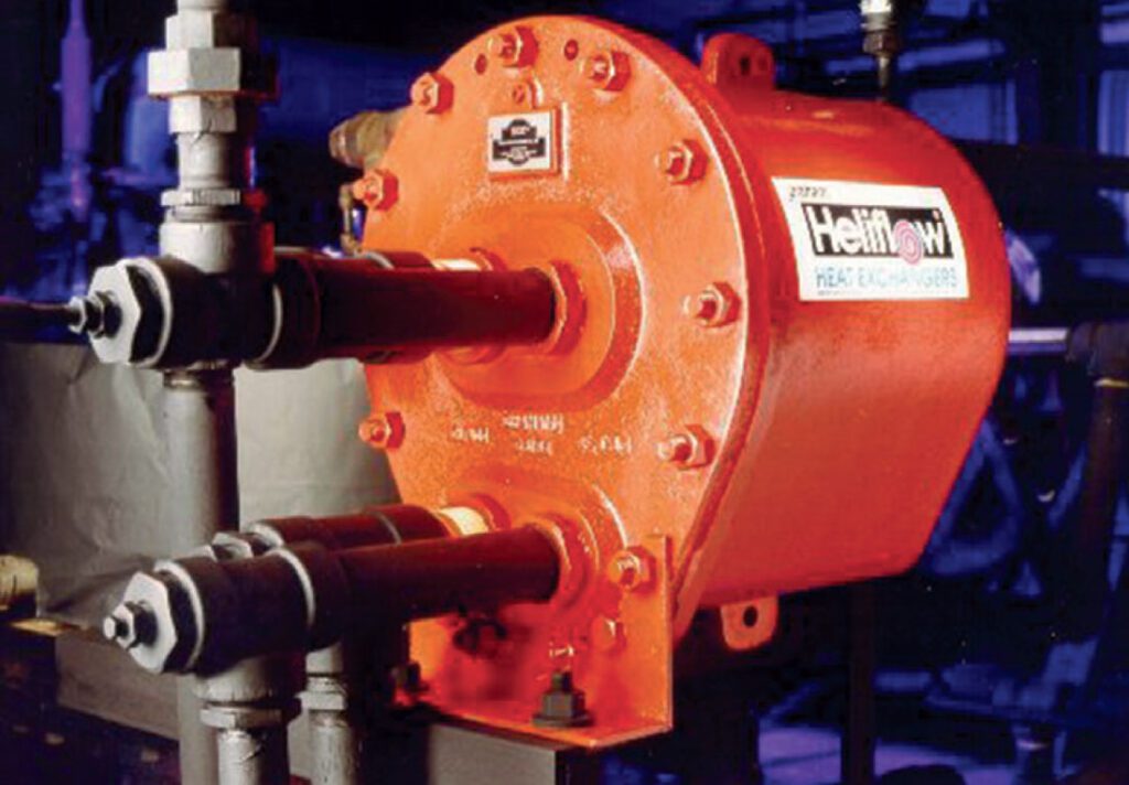
Supercritical fluids require a high pressure and temperature environment; these types of applications are well suited to the Heliflow design. The unique spiral tube design of the Heliflow allows it to move freely under thermal cycling as the tube bundle is allowed to expand and contract as necessary. This movement helps alleviate the stress and thermal shock problems. To handle high pressure on the tube side as well as the shell side, the Heliflow is available as a WeldSeal (Figure 3). This option replaces the standard bolted design (Figure 4) and welds the baseplate to the casing, allowing the shell side to handle pressures up to 340 barg. The tube side can see up to 1000 barg. Many different material options are available for both the tube and shell side of the Heliflow. Standard materials include copper, 304 SS, 316 SS, while some more uncommon materials are Inconel, Titanium, and Duplex 2205. Graham as a rule builds to ASME standards and can provide U-Stamping. Other certifications available include Canadian CSA B51, European PED, and Malaysian DOSH.
Freeze condensers
Freeze condensers fall into two categories; the first includes vapours that condense, then freeze in the heat exchanger. The second category typically includes non-freezing condensable mixed with water vapor or another component, which does freeze.
Both applications are similar in that the objective is to condense and remove from the vent stream as much of the vapor component as possible. The most effective method is to cool the vapor below its freezing point, however, once a component begins to freeze, the heat transfer rate is gradually decreased. To obtain the best efficiency, often two parallel units are used. One unit operates, while the other undergoes a thaw cycle. Heliflows are often used in the field of freeze condenser technology.
Conclusion
Certainly, there are applications that are better suited for different heat transfer technologies, but the purpose of this article is to outline the benefits of adaptive and multi-faceted equipment. The Heliflow technology proves the advantages of a compact and lightweight heat exchanger.
 About the author
 About the author
Carla Dias is Heat Exchanger Product Manager for Kinder-Janes Engineers. She has a study background in Civil Engineering, but has since specialised in the mechanical industry. Carla has been working with centrifugal pumps for almost 15 years and since joining Kinder-Janes 3 years ago, she has broadened her focus to working with the heat exchanger sector.