
In this series of articles we will look at the idea of heat transfer enhancement. The benefits of enhancement are that your heat exchangers will provide the same performance at a lower cost or provide better performance at the same or smaller overall size and footprint.
By Himanshu Joshi, Heat Exchanger Specialist, and Lou Curcio, Heat Transfer Advisor
In this part we will present more information on the enhancement types which were listed in Part 1, by elaborating on the following aspects: a more detailed description, which technique is applicable, and which side (shell or tube) is the best for enhancement. One important consideration in choosing the appropriate technique is the idea of “controlling resistance”, i.e. which component of the overall heat transfer coefficient is most beneficial to enhance.
Controlling resistance
Repeating from Part 1, the heat duty is represented by equation (1):
| Q = U * A * ∆T | (1) |
Which can also be written as:
| A = Q / (U * ∆T) | (2) |
Q = heat duty [W]
U = overall heat transfer coefficient, OHTC [W/m2–C] A = heat transfer surface area [m2]
∆T = Temperature driving force for heat transfer [C] Equation (1) shows that we can increase the heat duty by increasing the surface area and/or the OHTC, given the two flow rates and their incoming temperatures are fixed. Let’s begin by looking at the OHTC, and how it is calculated. The OHTC for a heat exchanger with two fluids, one hot and one cold, is expressed by the following equation:
| U = 1 / Rtotal | (3) |
| Rtotal = Rhot + Rcold + Rfouling + Rwall | (4) |
Rhot and Rcold are determined based on the individual convective film heat transfer coefficients, which depend on the fluid properties, flow conditions, and the geometry of the heat exchanger. A thermal design is optimal when the Rhot and Rcold values are equal. This design may sometimes be infeasible due to constraints like pressure drop or mechanical limitations. In certain designs, one thermal resistance can be significantly greater than the others, and it is known as the Controlling Resistance. An example of this concept is the design of air-cooled heat exchangers. Often, the thermal resistance on the airside with bare tubes is the Controlling Resistance due to the low film heat transfer coefficient of air compared to that of the tube side fluid. When this situation arises, the thermal design will benefit from enhancing the airside with external, high fins. The fins significantly increase the outside surface area, which reduces the airside thermal resistance. In this example, the Overall Heat Transfer Coefficient (OHTC) decreases because it is based on the finned surface area instead of the bare tube area. The additional surface area from the fins overcomes this deficit, resulting in an increase in Q. There are two lessons from this example. First, the design is enhanced by reducing the Controlling Resistance using an appropriate enhancement technique, namely external high fins. Second, the combination of the OHTC multiplied by A must increase for the enhancement technique to boost Q.
Enhancement types
Four types were listed in Part 1, we will look at each in detail below.
Increased surface area
Surface area can be increased simply by making the heat exchanger larger – more tubes and a larger shell diameter. This approach has many drawbacks – higher purchase cost, decrease in OHTC, lower velocities and higher fouling if the fouling is velocity dependent, and the possibility of poor flow distribution. Additionally, this approach cannot be used in debottlenecking situations where the shell size is already fixed. The most common technique to increase the surface area, without making the heat exchanger larger, is by forming or attaching fins on the outside of tubes. In shell-and-tube heat exchangers the fins are formed from the base tube material and such finned tubes are commonly referred to as Low Fin Tubes, here we will call them Integral Fin Tubes (IFT). A sample tube is shown in Figure 1.
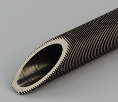
Fin Tube.
IFT provide 2.5-3.0 times the surface area compared to smooth tubes and are therefore ideal for use when the controlling resistance is on the shell side. In chemical process industries IFT can offer benefits for shell side condensing or gas flows, and occasionally with liquid flows.
IFT are made by starting with a smooth tube and using the tube wall material to form the fins. The OD (outside diameter) of the finned tube, measured at the top of the fins is the same as the smooth tube. This results in a tube wall thickness, under the fins, which is smaller than the starting smooth tube. For corrosion or pressure retention, it is the new, smaller wall thickness that is relevant, not the starting thickness. Secondly, the ID (inside diameter) of the finned tube is smaller than the starting smooth tube which increases the tube side pressure drop, a consideration in the thermal design. A myth about IFT is that, compared to smooth tubes, fins make the shell side more prone to fouling and IFT are more difficult to clean with traditional hydroblast techniques. This thinking has taken hold because of the mental picture of foulant material getting trapped in the gap between the fins. However, the experience of the authors in over a dozen fouling services and that of IFT manufacturers has never borne out this fear. IFT fouling is governed by the same mechanisms as those for smooth tubes and they foul at the same rate. With an area increase of 2.5-3.0X, the finned heat exchanger can provide that much extension in run length before the same fouling level is reached, we will elaborate on this in a future article.
Increase the heat transfer coefficient
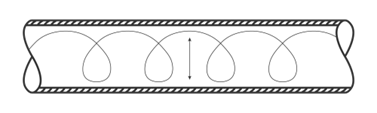
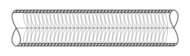
The heat transfer coefficient is a strong function of velocity and turbulence in single phase flows. Enhancement techniques can be applied on the tube side when it is the controlling resistance. Two such techniques are available, inserts and internal fins (ribs). Tube inserts create improved mixing at the wall and thus improve the rate of heat transfer. Spring-like wire inserts (Figure 2) provide 1.3-1.5X improvement while wire matrix inserts (Figure 3) can provide as much as a 10X increase if the flow is laminar. Internal ribs are shown in Figure 4 (tube ID). They create a swirl flow and increase the tube side heat transfer coefficient, additionally providing a small increase in the surface area. In boiling services the heat transfer coefficient can be increased by improving the nucleate boiling ability of the surface by providing a large number of nucleation sites (tube side or shell side). A specially designed surface coating or fin-like structures formed from the tube material (Figure 4, tube OD) are available and proven. Details of these techniques will be covered in future articles.

Internal Ribs on the tube side. Photo courtesy of Wieland.
Decrease the Fouling Resistance
If fouling is the controlling resistance, several techniques are available to reduce fouling and thus increase the OHTC. These were described in the series Fouling Focus (Parts 4 & 5, Heat Exchanger World Dec 2023 and Feb 2024). The techniques include tube inserts, coatings, vibration, and a change of tube metallurgy.
Change to non-tubular heat exchangers (plate-type)
Heat exchangers such as Plate-and-Frame, Spiral, Plate-Fin, and Plate-in-Shell offer several advantages — compactness (smaller size, volume, and plot-space), higher OHTC, and lower fouling. Selecting one of these, either as an initial design or as a replacement requires consideration of several factors including cost, reliability, and pressure drop. We will address plate-types in a future article in this series.
Pressure drop
In general, an increase in the heat transfer coefficient for single phase services comes at the price of pressure drop. When we use inserts or increase velocity, there is an added pressure drop that must be accounted for in the overall cost of using the technique. Technology suppliers have data and experience to advise how much extra is needed.
Upcoming in this series
In upcoming articles, we will look at details of specific technologies available for heat transfer enhancement – how they work, advantages and disadvantages, applicability, precautions to be taken, costs, maintenance aspects, and field experience.
About the author
 Himanshu Joshi retired from Shell in 2021 after 34 combined years with ExxonMobil and Shell, during which he specialized in heat exchangers and fouling. He was part of a team that was granted a patent related to fouling deposit analysis at ExxonMobil, and led applied fouling R&D projects at both companies. He has made several presentations about the field aspects of fouling and fouling mitigation, and deployed many mitigation technologies in the field. He can be reached by email at alph.hmj@gmail.com.
About the author
 Lou Curcio has over 30 years of experience in design, troubleshooting
and repair of all types of heat exchangers. Leader of technology
development projects and advisor for ExxonMobil’s global manufacturing
teams. Co-inventor of two U.S. patents and co-author of papers on
enhanced heat transfer and fouling of heat exchange.
About this Technical Story
This Technical Story was first published in Heat Exchanger World Magazine in March 2025. To read more Technical Stories and many other articles, subscribe to our print magazine.
Technical Stories are regularly shared with our Heat Exchanger World community. Join us and share your own Technical Story on Heat Exchanger World online and in print.