Without a doubt, the heat exchanger is an essential and critical component in all thermal systems, whether for industrial use (chemicals, petrochemicals, iron and steel, food processing, energy production, etc.), for the automotive, aeronautical and aerospace industries, or also for the building industry (residential or commercial).
By Christophe Weber and Quentin Blondel, GRETh – Heat Exchanger Research Group
Indeed, it is generally agreed that more than 90% of the thermal energy used in industrial processes passes through a heat exchanger at least once: it is therefore an essential and ubiquitous element for the proper operation of processes but also in the energy performance strategy framework. First of all, as a reminder: a heat exchanger’s main function is to transfer thermal energy, generally from one fluid to another at different temperature levels. The heat exchanger functions are extremely different and varied. Among others, we can mention the following main application cases:
- Liquid or gas heater or cooler;
- Heat recovery system;
- Thermal heater (as radiator);
- Dehumidifier or partial moist air condens
- Evaporator or condenser;
- And many moreer;
It should be highlighted here again that all these functions are performed by a single component type: the heat exchanger.
Efficiency and pinch minimization
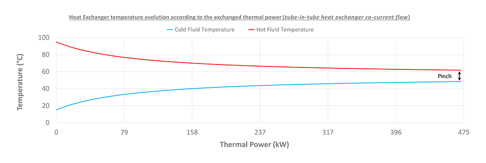
From an energy point of view, the most efficient heat exchanger will be the one that will allow transfer of the most important thermal power amount through it (notion of pinch minimization, i.e. the lowest temperature difference between the two fluids within the heat exchanger) with a minimal heat transfer surface (thus considerations of material and volume) and at the same time minimizing the pressure losses which affect the consumptions of the auxiliaries necessary for the fluid’s circulation (pumps, fan, compressor).
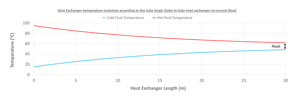
However, pinch minimization leads paradoxically to an important increase of the heat transfer surface (and therefore the quantity of heat exchanger material and its cost) as well as very often the pressure losses (more heat transfer surface and therefore potentially more heat transfer length and thus more pressure losses). From a more concrete point of view, and based on the simple example of a tube-in-tube heat exchanger, it can be observed and understood, thanks to the figure below, the following points:
1. The more efficient the heat exchanger, the lower the pinch and therefore the higher the thermal power transferred;
2. Thus, the more efficient the heat exchanger, the larger the heat transfer surface and therefore the longer the heat exchanger will have to be. Consequently, the pressure losses increase and generate a higher energy consumption (auxiliaries power consumption);
3. However, it is clear that the more we want to reduce the pinch, the greater the required effort on the length and therefore over the heat transfer surface.


We point out that the previous remarks 2 and 3 can be subject to some nuances: beyond the heat transfer surface growth due to the length increase, as mentioned in the previous example, there are other possibilities in order to improve the heat exchanger efficiency (or to decrease the pinch). Indeed, the heat exchanger pinch can be reduced by:
- Increased heat transfer surface through the use of secondary heat transfer surfaces such as fins (and therefore without impact on the length of the heat exchanger itself);
- The heat transfer intrinsic performance growth (quality increasing of the heat transfer) by means of intensification devices such as, for example and among others, turbulators/inserts, specific surface structuration such as micro-grooved tubes or corrugations, etc.;
- The combined improvement of the heat transfer surface and the heat transfer quality through the implementation of secondary heat transfer surfaces with specific surface structuration, such as segmented fins, offset strip fins (OSF), etc.
One of the rational energy management challenges is to use, among other things, technologies that optimise these different criteria.
Appropriate sizing
Beyond the heat exchanger’s technological development, it is also possible to bring a concrete answer in order to improve the global energy efficiency of the processes using them: this is expressed by their appropriate sizing. The heat exchanger sizing consists in the determination of the heat transfer surface necessary to obtain the desired performances (power, outlet temperature). At the same time, it is necessary to determine the pressure losses generated by the fluids circulation (due to friction against the walls as a result of the material roughness and the fluid viscosity) in order to verify the conformity with the specifications and the latter’s objectives.
Obviously, a well-adapted, correctly sized, well-manufactured and correctly used heat exchanger allows a significant improvement of the process efficiency and therefore of the energy consumption. However, the sizing operation remains quite delicate and often not very precise because it relies for a large part on empiricism (so complex is this science that is called thermal).
It is thus often common to take sizing precautions and assumptions which lead designers and engineers to design heat exchangers that are often oversized and consequently not fully optimised (oversizing margin more or less important). However, this oversizing is wise from the designer’s point of view. Indeed, during the real heat exchanger operation, this reduces the risk of the heat exchanger not meeting the requirements of the initial specifications: corresponding to an undersized heat exchanger case (unreachable performances). This case is undoubtedly much more problematic than a bad optimisation (important oversizing).
Ensuring design quality
Beyond this energy aspect and its optimisation, it is important to keep in mind the reality on the ground: energy optimisation is often not a priority (unlike development time and cost, manufacturing/installation/maintenance time and cost, return on investment, etc.) and satisfying a process objective is often the most important. It is therefore necessary to focus on this aspect and sizing a heat exchanger that fits it.
The heat exchanger thermal-hydraulic sizing requires a set of preliminary data, which are more or less restrictive, and which will greatly determine the quality of the design. From a project phasing point of view, the following 8 main steps can be established, which are considered essential for the success of such projects:
1. Drafting of the heat exchanger specifications: definition of the existing process input data
(temperatures, pressures, flow rates) & the desired output data (temperatures, pressures/pressure drop); characterisation of the fluids used and their specificities (saturation, critical and solidification properties, possible degradation/decomposition risks, ATEX risks, fouling/clogging type and risks, toxicity and corrosion risks); taking into account the system integration characteristics (dimensions, available space & associated compactness);
2. Design point identification: definition of the most disadvantaged operating case from the heat exchanger’s overall performance (i.e. the one which requires the largest heat transfer surface);
3. technological selection: choice of the heat exchanger type that best fits all the specifications (for example when a compromise between compactness, risk of clogging, and inspection/maintenance is required);
4. thermal, hydraulic and mechanical design: as mentioned above, heat exchanger sizing is a complex exercise and often subject to numerous assumptions. In addition to the previous essential steps, it requires the selection of a suitable heat exchanger modelling method according to the heat transfer type (single-phase, evaporation, condensation), the selection of appropriate
heat transfer and pressure drop laws for the specified geometries and heat transfer type, and the calculation of the required dimensionless parameters for the correlation validity range. This thermal-hydraulic design must necessarily be combined with a consistent and realistic mechanical design and with the standard manufacturing possibilities to meet the standards and mechanical calculation codes in force;
5. Real operating conditions simulation and variation: once the heat exchanger has been sized at its design point, the real operating conditions are often far from the said design point and it is therefore often necessary to evaluate the real heat exchanger performance for the other operating conditions. This allows us to know the variation range of the main operating criteria which will be used for example for the system regulation;
6. manufacturing: with respect to the specifications from the thermal-hydraulic and mechanical design;
7. Integration to the complete system including the recommendations of the expert to ensure, for example, a good fluid distribution in the heat exchanger and proper arrangement, if necessary, of the metrological devices which will be used for the process control and the performance tests;
8. Performance and conformity tests, in particular with acceptance tests in real operating conditions previously simulated.
These phases and an in-depth analysis by the experts will greatly determine a project’s success. For example, the choice of an ‘A’ heat exchanger technology, which is initially much more expensive than a ‘B’ heat exchanger technology, may turn out to be the best solution considering the process compactness requirement and the great maintenance and cleaning difficulty, leading to a prohibitive operating cost in the ‘B’ case, which initially seemed to be the least expensive. In order to clearly understand the importance of the statements and steps defined in the previous paragraphs, we provide in the following a short experience feedback on a simple case which illustrates the consequences of the above mentioned steps not being respected.

Case study
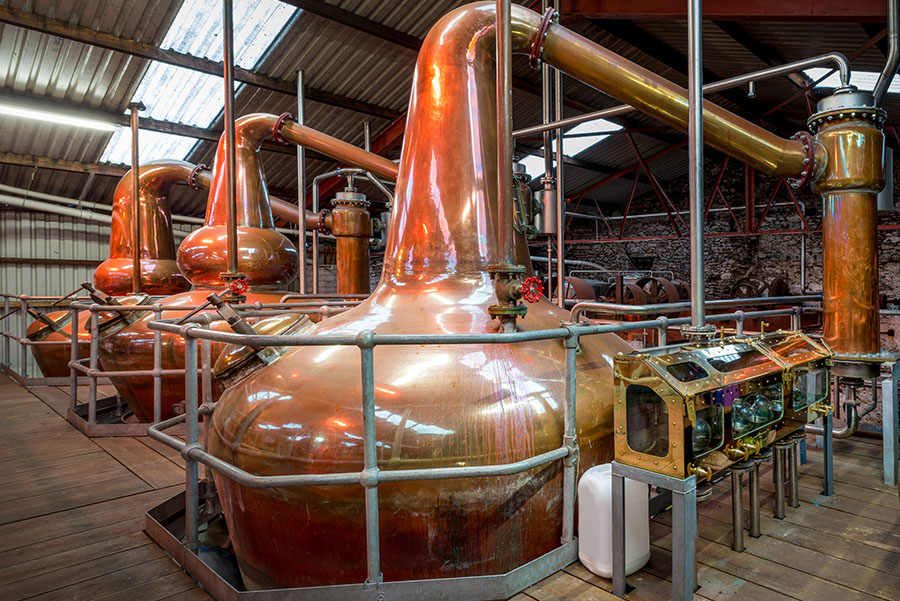
A customer, a spirit producer, had a new production plant built and was looking to increase the production rate in order to meet the growing demand of his consumers. Within the framework of the alembics realisation, which remains a key point of the production process, one of the key components is the condenser of the system which allows to recover the alcoholic vapors condensate. The initial project purpose was to double the condensate capacity due to the overall process production increase. The plant, built many years ago, was working perfectly and the customer asked a heat exchanger manufacturer specialised in copper alembics to design a number of new condensers to double the condensate flow. The design was carried out by the said company and the condensers were manufactured and installed.
Unfortunately, the first performance tests on site did not give satisfaction since the condensate flow rate obtained was 30% lower than expected, thus not fulfilling the customer’s objectives. An expert evaluation took place and one of the first points analysed was the design of the condensers. Technical justification notes were requested from the supplier; however, the latter was in fact unable to provide a detailed and substantiated calculation note. In fact, after investigation, the supplier’s idea was to consider that the condensate production capacity could be doubled by extending the heat exchange surface compared to the initial condenser (shell-and-tube technology) which was satisfactory. The supplier initially wanted to double the tube length, but an integration constraint did not allow this adjustment, so the heat exchanger was provided with a doubled heat transfer surface by means of the tube bundle duplication.
Nevertheless, no analysis of the internal and external flows was carried out. This led to this malfunction (30% lower condensate) because the internal heat transfer phenomena, and in particular the single-phase glycol water circulation, although easy to determine, were not subjected to the appropriate calculation analyses.
Indeed, as the fluid makes only one pass inside the tubes, the bundle duplication (i.e. a multiplication by 2 of the tubes number) has led to an increase by 2 of the available cross section for this fluid and thus divided by 2 its intra-tubular speed; or simply illustrated as:

This decrease in liquid velocity led to a change in the flow regime from an initially transient flow (close to the turbulent flow) to a laminar flow. This change, although easily identified, was not anticipated by the manufacturer and therefore resulted in a drastic decrease of the heat transfer coefficients, which is the main cause of the underperformance observed during the commissioning of the heat exchangers. In this context, intensification techniques such as inserts could have been used to compensate for this performance reduction, but the process constraints did not allow for such devices. Thus, only a complete redesign and a new manufacturing of the device could ensure that this problem was overcome.
In parallel to this analysis, the complete study carried out by GRETh has allowed us to identify operating margins on the specifications and to optimise the design of the heat exchanger. It should be noted that the critical point was not at all related to the complex thermal phenomenon to be evaluated, which is the extra-tubular multi-component mixtures condensation of alcoholic vapors with non-condensable gases, but only on the single-phase part which was the condenser thermal brake (higher thermal resistance).
Conclusion
This short case study shows the essential value of the expert’s knowledge, but it also reminds us of the imperative need to master, through training and feedback from associates, customers and previous generations, the knowledge of sizing and best practices necessary to achieve an optimised design that correctly fulfills the needs.
It can be said that there is no engineering field which is not faced with thermal issues, which makes the thermal knowledge necessary and if not essential, then strategic. Thus, it is advisable today, in our opinion, to also maximise efforts towards learning and raising awareness of current and future actors to new technologies and good design practices that will lead to appropriate technological developments and choices, and consequently to well sized heat exchangers: in a word, efficient heat exchangers for an efficient industry.


About the authors
Christophe Weber, PhD, is a thermal engineer and heat exchanger expert with more than 10 years experience and has been the GRETh association’s CEO since 2017.
Quentin Blondel, PhD, has been an R&D thermal engineer within GRETh since 2021 and is notably in charge of technical and scientific studies and related report writing.
About GRETh
the GRETh – Heat Exchanger research group – federates for 30 years industrial experts and academics in the thermal and heat exchanger-related fields, through 6 main activities:
- Network
- Technical and scientific documents watch and provision
- Echtherm heat exchanger software provision
- Technical and scientific hotline
- Expertise and specific studies
- Training courses
For more information, contact: info@greth.fr

