
Material selection is a critical factor for heat exchangers working in corrosive applications, but tube expansion methods may also play a role in tube life. Premature tube failure is one of the leading causes of downtime in the field, accounting for 47% of lost production opportunities (Stewart, M. & Lewis, O., 2013). Stress corrosion cracking is a common tube failure mode in corrosive environments, impacting any number of tubes in a vessel. While stress corrosion can be difficult to identify in the field, there may be a way to reduce the likelihood of occurrence by changing the tube expansion method.
Content adapted from research presented by Ben Lambers & John Papie, Elliott Tool Technologies
Background
In 2023, Elliott Tool Technologies was approached by a Heat Exchanger Fabricator with questions about a new Titanium marine vessel they put into service a year prior. Several of the tube ends were severely damaged and cracked along the expanded ID of the tube. It was determined that this failure was likely caused by stress corrosion cracking as a result of the expansion process.
Stress corrosion cracking
Stress corrosion cracking is a type of fracturing that occurs in metals due to a combination of tensile and residual stress in a corrosive environment. This can occur in stainless steel, titanium, and Inconel materials, impacting any number of tubes in a vessel. Tube failure related to stress corrosion cracking will often result in retubing, as the tube is often too brittle to be plugged or repaired by other means. Two types of stress corrosion cracking are intergranular, when cracks develop along grain boundaries, and transgranular, where the crack forms through the grains of the material.
Indicators of stress in metals
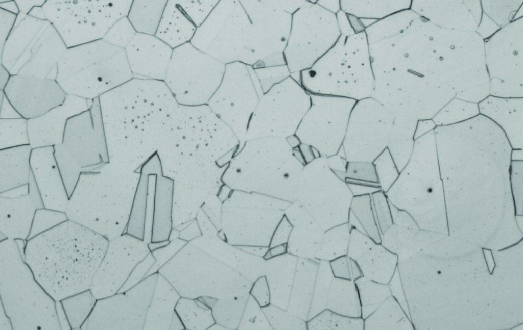
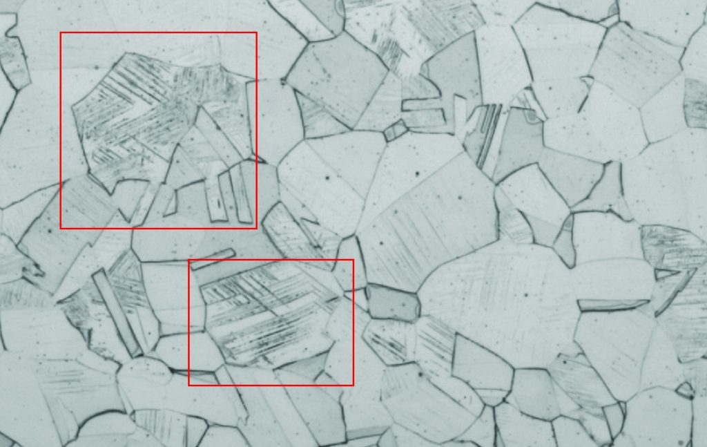
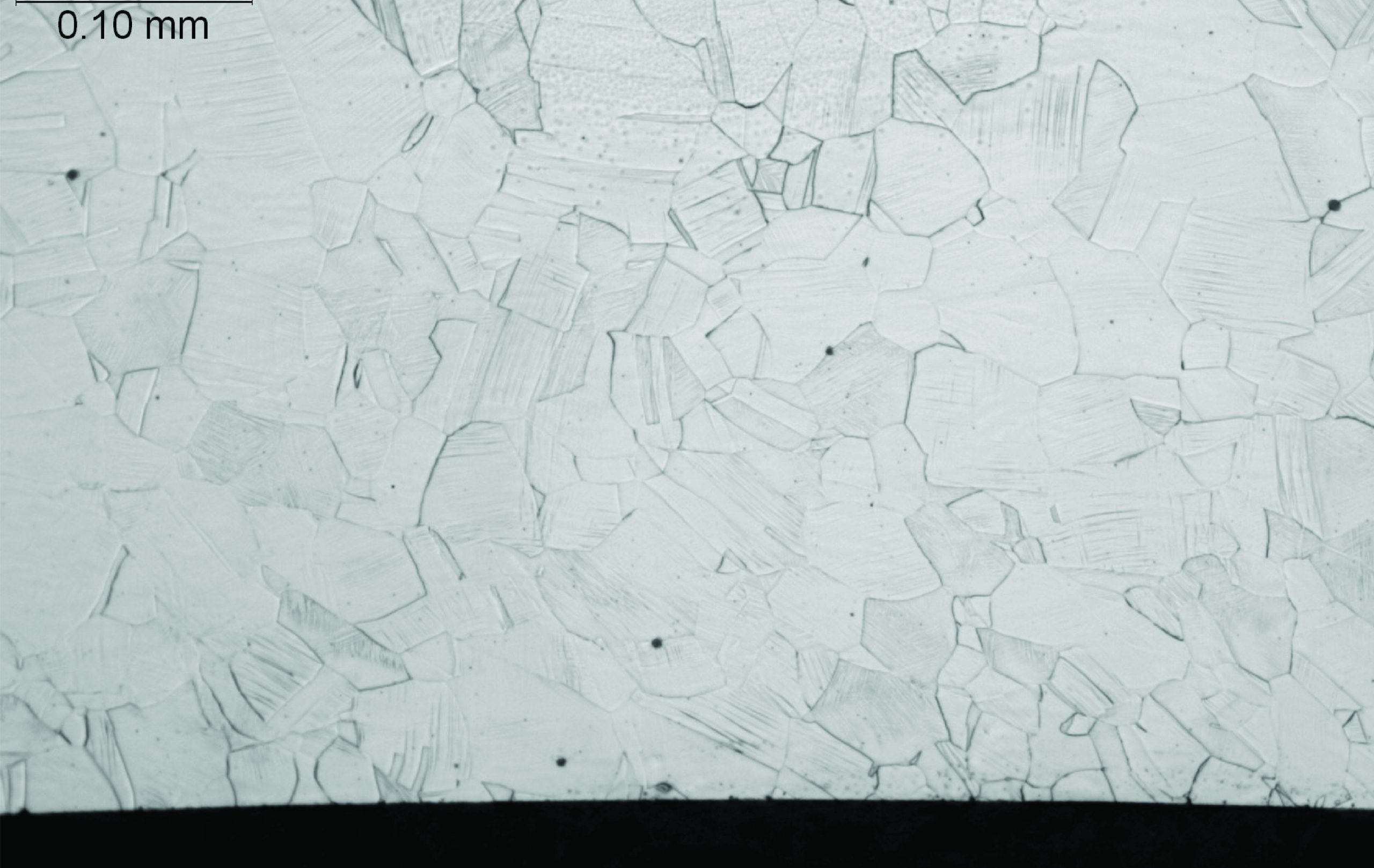
There are many different sources of residual stress in heat exchanger manufacturing, from welding to tube trimming. Due to the method of failure identified in the customer’s Titanium vessel, Elliott wanted to explore how the residual stress produced during the tube expansion process might impact tube material. There are two indicators of stress in metals: hardness and shear banding. All metals will see some level of hardness change with cold working. The permanent change to the grain structure from plastic deformation will increase the hardness in affected areas. Since tube expansion causes plastic deformation in the grain structure of the metal, it will result in a higher hardness and potentially cause defects in the metal. Shear banding is another method to determine how much stress was imparted on the metal. Shear bands are a microstructural feature that develops in the grains as a result of deformation. Shear banding increases with the degree of deformation. A 2013 research conducted by Bai et al, showed a correlation between increased shear banding and stress corrosion cracking, specifically in 300 series stainless steel (2013). This type of testing is destructive as a cross section must be cut through the material in order to identify it. Shear banding presents as lines appearing inside the grain boundaries, as shown in Figure 2.
The experiment: does tube expansion method impact hardness & shear banding?
Two types of expansion methods
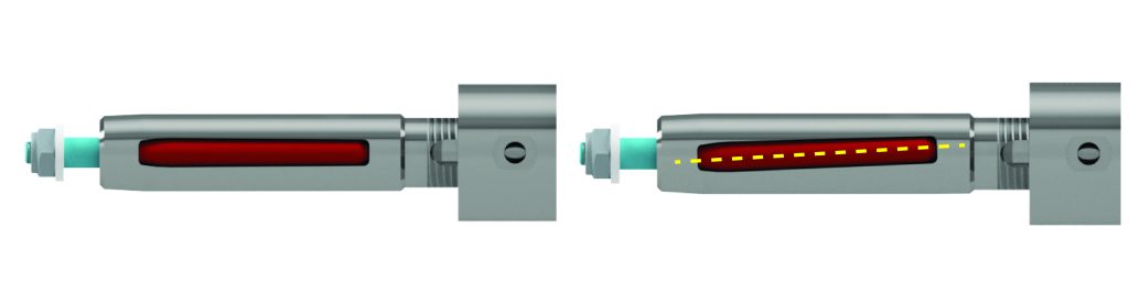
Two types of mechanical expanders are parallel and tapered roll expanders. Parallel Roll, also referred to as Parallel Pin, is designed so the roll and expander are aligned with a zero-degree feed angle. This orientation requires an outside force to act on the mandrel to drive it forward, typically done using a hydraulic or electrically driven system. Alternatively, tapered roll expanders use a feed angle on the roll orientation, allowing the mandrel to draw forward as the tool is rotated.
Initial research: explanation of initial testing and results
In 2023, Elliott Tool Technologies presented findings of research comparing parallel and tapered roll expansion on SA213 304L ¾” x 14 BWG average wall tubes. Using these existing samples, Elliott decided to further investigate the differences in the micro hardness through the inner wall of the tube, as well as the metal structure after expansion. The samples were then sent out to Metallurgical Solutions Inc and Webco Industries for evaluation. While this test was not statistically significant, it did show some differences in both hardness and structure between the two methods. These initial findings, combined with the research conducted by Bai et al., Elliott determined that further testing was necessary.
Testing methods & reasoning
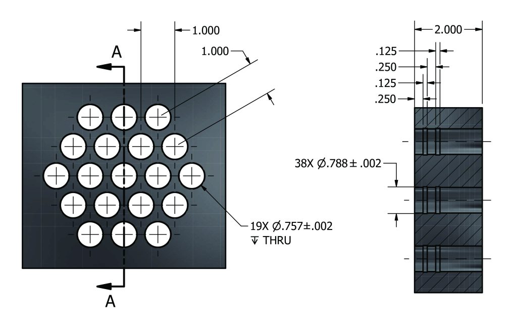
The material to be tested was SA213 316 Stainless Steel, ¾” x 14BWG minimum wall tubing expanded into 2” thick 316 Stainless Steel tube sheets. The tube sheets for this experiment had 19 tube holes each and were manufactured by Elliott Tool Technologies to meet TEMA standards for triangular pitch and tube sheet hole grooves, as seen in Figure 4. All tubes were all expanded in one operation using Elliott’s Ultra Hawk assisted rolling system at 600 RPM. The tested tools utilized common components, with roll orientation being the only difference.
Test results: greater evidence of shear banding in tapered pin at higher wall reduction
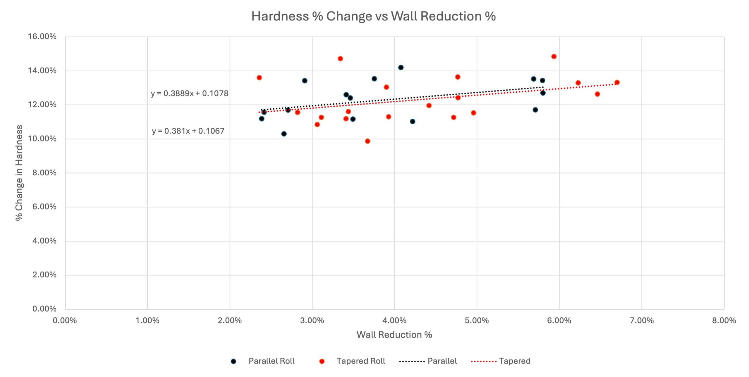
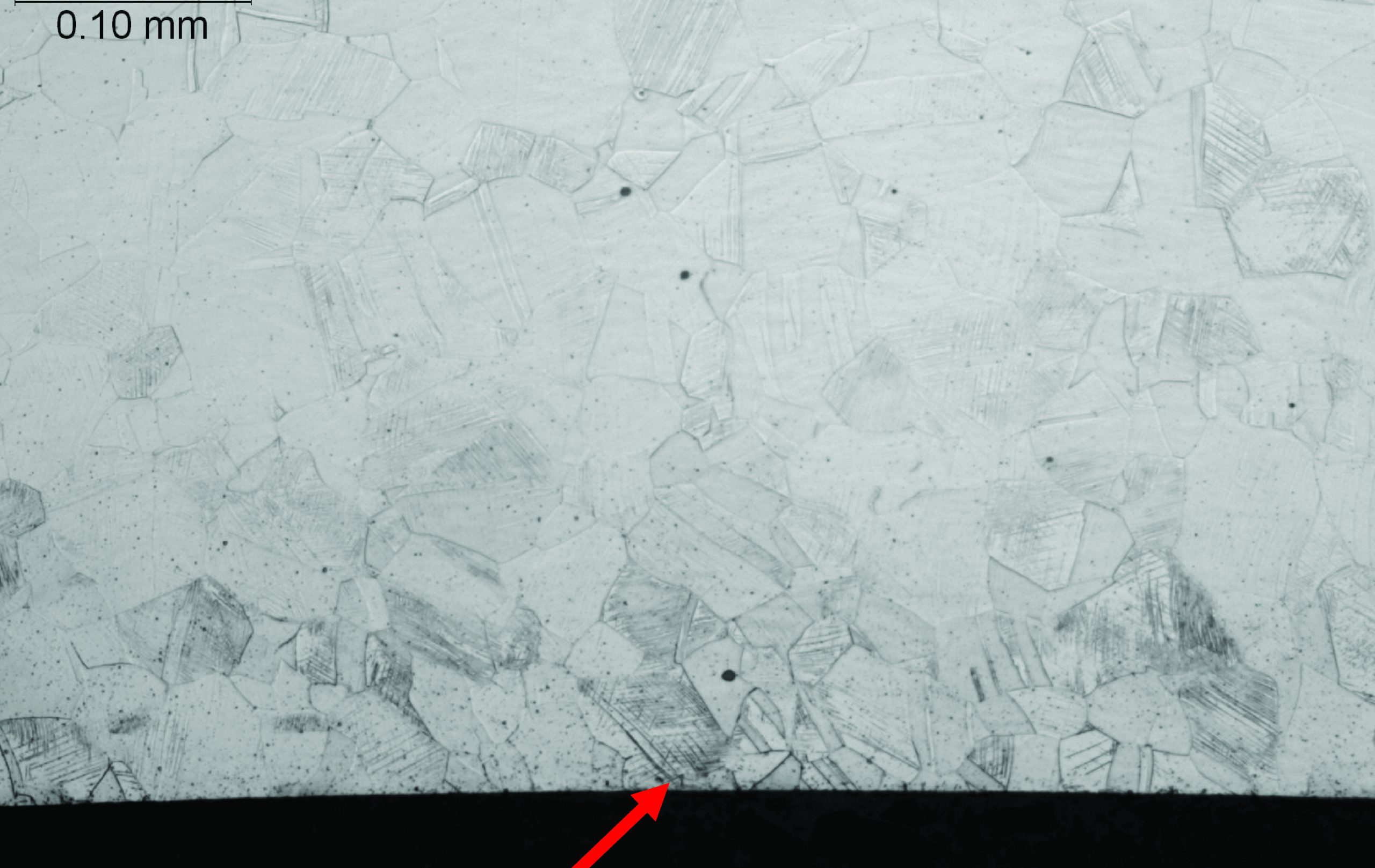
After the tubes were expanded, the tube sheets were sectioned using a wire EDM to cut the full length in half. Samples were then evaluated a location 90° relative to the EDM cut and at the midpoint between the grooves. Surface hardness curves were observed as being almost identical between the two types over the 19 samples of each that were evaluated. Metallographic samples showed at 3% and 4% wall reduction the difference in identifiable shear bands is roughly the same. At 6% wall reduction, the differences become more pronounced, aligning with previous results. Figures 6 & 7 show etched microstructures at 200x magnification. Both samples indicate some level of shear banding, but the tapered pin image shows a higher amount of shear banding on the ID surface of the tube. Elliott attributes this to be a result of the tapered roll expander generating drag on the surface during expansion. Based on the metallograph results it suggests the shear banding difference at the surface will cause an increase in the potential for stress corrosion cracking.
Conclusions & industry implications
Premature tube failure is one of the leading causes of downtime in the field. Reducing any avenue for tube failure can help reduce downtime and costs. Since stress corrosion cracking failures can affect many tubes simultaneously, fi nding methods to reduce the likelihood of cracking would greatly reduce the cost of emergency repairs or retube efforts. Based on Elliott’s research, stress corrosion cracking is more likely to occur at higher wall reduction percentages (≥ 6%), with tapered roll expansion producing more pronounced shear banding. As a result, parallel pin expansion could reduce the likelihood of this type of failure from occurring by limiting the stress imparted on to the surface during expansion. Elliott Tool Technologies is committed to finding solutions to industry problems and committed to continuing to improve the body of knowledge of heat exchanger fabrication. Some points for future study include examining the mandrel rotation speed and mandrel drive speed in parallel pin mode, as well as looking at the overlap area in step rolling applications.
References
Bai, T., Chen, P., & Guan, K.S. (2019).
How do nickel and Inconel alloys perform in caustic media. Heanjia Super Metals Co. Ltd. https://super-metals.com/news/how-do-nickel-and-inconel-alloys-perform-in-caustic-media/
Stewart, M., & Lewis, O. T. (2013).
Heat exchanger equipment field manual: Common operating problems and practical solutions. Gulf Professional Pub.
About this Technical Story
This Technical Story was first published in Heat Exchanger World Magazine in February 2025. To read more Technical Stories and many other articles, subscribe to our print magazine.
Technical Stories are regularly shared with our Heat Exchanger World community. Join us and share your own Technical Story on Heat Exchanger World online and in print.