
Heat exchangers are some of the most common equipment types in industry. Their range of application is quite wide, spanning from marine environments and chemical processes to energy, power plants, refineries and more. The design period of a heat exchanger takes into account thermal and mechanical calculations and pre-manufacturing periods. To build on existing general knowledge about the thermal side of design, manufacturers need to be more considerate of other parameters.
By Enes Kuzey Er – R & D Specialist, Ekin Endustriyel
Beyond technical data sheets
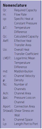
To design a heat exchanger, the designer needs to make sure that the required heat transfer between two streams will be achieved. The starting point of a heat exchanger design is the first law of thermodynamics. After determination of the capacity, the heat transfer formula below is applied to have overall heat transfer coefficient (Uo).
* Qr = m × cp × ˜T
* Qc = Aeff × U0 × LMTD
It is clear that the main goal of a design process is to have an acceptable heat transfer rate and pressure loss. Yet there are more factors that need to be considered. Let’s take a look at one of the most common types of heat exchangers: Plate type heat exchangers.
Turbulence
The heat transfer rate is directly effected by the type of flow. Turbulence causes better heat transfer beside laminar flow. To have turbulence in the channels of a plate heat exchanger, the Reynolds number must be more than 2200. The Reynolds number is a function of velocity occuring in the channels. A fewer number of channels means higher level of turbulence yet also higher pressure losses. So, the balance between these parameters is important.


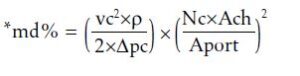
Maldistribution
Plate heat exchangers are known by efficient heat transfer since their compact structure. Flow distribution area is the guide for streams flow through channels. The fluid flows by this guidance to outlet ports. Yet this path might result a problem for viscous fluids. Maldistribution is our decisive parameter in such cases. Definition of the maldistrubution is blind spots exist in a plate. A high percentage of maldistrubtion with the fluids having viscosity over 20 cP may cause far less level of heat transfer than required.
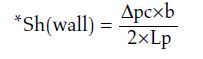
Wall shear stress and fouling relation
Wall shear stress is the force the fluid exerts on the plates to keep the molecules suspended in the flow. Naturally, it increases with the increasing presssure losses. On the other hand, the nature of fouling depends on the working conditions and must be taken into account. Fouling factors are used all around the world, and are provided by different associated organizations and institutions. The traditional fouling factor is ”0.0005” and it will cause 30-40% increase of the effective heat transfer area. This might seem safe and effective, but it will result in an increased number of channels. As an outcome, velocities will decrease and the vortex effect will become less impactful.
Besides usage of excess area, a more useful way to prevent fouling is to check shear stresses on the wall. As a numerical limit value, 50 Pa would be enough to design a heat exchanger able to self-clean with the sweeping caused by the high shear stress on wall. If the fluid is so viscous that it is not possible to reach this value, then our minimum level of shear stress should be at least 30 Pa. Higher shear stress means higher self-cleaning capabilities. Also, another topic to consider in this situation is operating the heat exchanger according to its design parameters. Operating the heat exchanger with half capacity will cause fouling over time since the channel velocities become lower and self-cleaning is less effective.


Differential pressure
Differential pressure is the pressure between the opposite sides of the plate. A heat transfer plate holds steady while fluids flow through each side without mixing. During continuous flow, the forces applied by fluids effect the plate from both sides. Alongside the working pressure values, the difference between the values is critical as well. From a general perspective, we could say that the limit for differential pressure is 5 bar for a standard liquid-to-liquid heat exchanger, but it is not possible to determine for sure without knowing plate geometry and material. A designer must consider these factors or it could lead to fatal effects for the heat exchanger, such as bending of the plate.
Channel arrangement
Plate heat exchangers have numerous types of configurations thanks to having low and high theta heat transfer plates, chosen for whether they gain more heat transfer or fewer pressure losses. A channel formed with both high theta plates has high heat transfer, and the same goes for L theta plates. A formed channel has lower pressure losses in this case. When high theta and L theta plates form as a channel, the channel has mixed characteristics of both and is referred to as the M channel. The channel arrangement depends on process data. The designer should consider permissible pressure drops, temperature profile, viscosity of fluids, phase changes, and many other factors, in order to deal with possible future problems.
To choose the best configuration, an optimization program would be useful. An optimization algorithm can be easily created since our main goal is lower the costs. To do that, the algorithm should minimize the number of plates among all possible configurations created with a combination of different plates and passes.
Also another topic should be mentioned is channel arrangements importance for after sales works. Complex channel arrangements would cause complications for customer and cause problems for periodic maintenance. If there is not other obligation it is desirable to have channel arrangement for full of H theta or L theta channels. If it is not possible, channel arrangement should be symmetrical for M, H or L theta channels on primary and secondary circuits

About the author
Enes Kuzey Er is the Heat Transfer Product Sales – R&D Specialist for Ekin Endustriyel, responsible for sales of heat transfer products such as plate type heat exchangers (gasketed or brazed) and shell and tube heat exchangers. He is also researching solutions for industry needs through customer feedback, and provides support for related research and development processes.