Dr Giuseppe Tommasone has been working with plate heat exchangers (PHEs) since 1979. Over the years, he has collected commonly asked questions about the equipment. Here you can find all of the answers to those frequently asked questions in one place, put together over 40+ years of experience.
By Dr Giuseppe Tommasone, heat transfer consultant
Q1) Is it possible to accidentally mix two fluids in a PHE?

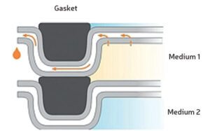
A) In principle no, due to double gaskets on the corner side where fluid is entering in the plate. In case of failure of the first gasket, the second will deviate outside leaking. For this reason PHE is used in food & dairy applications as a pasteurizer. In special cases (legionella risk, lubricant oil for transformers) a double wall plate is suggested; this provides further safety in case of possible holes in one plate, so the second keeps one fluid separate from the other (see Fig.1).
Q2) The fouling factor (FF) in the data sheet is specified for shell & tube heat exchangers; can I use the same value for PHE?
A) No, you should divide by ten. Fouling factors have been a topic of discussion for years. PHE FF must be 1/10 of shell & tube FF as API 662 recommends. There is a confusion among process engineers on FF to be used in PHE and often EPC contractors’ data sheets refer to FF for shell & tube. Investigations demonstrated that these values do not give good results in PHE since they often result in over-sized units with premature fouling due to reduced velocity and turbulence.
Q3) Material required in data sheets is 316L. Why is the PHE manufacturer only offering 316?
A) AISI 316L (low carbon with percentage lower than 3%) is required when welding is involved (for example, shell & tube units) – See Fig. 2. Plates are pressed without any welding, therefore there is no need for 316L as plate material. If connections are with stud-bolts with lining in NBR or EPDM, then the total unit is welding free. If connections are welding neck (like oil & gas applications in the Middle East) then 316L is better and WPS must be described.

Q4) For installation issues, I have to change the flow circuit: in other words, the primary side must be secondary side. Can I switch the sides in a PHE without any problem?
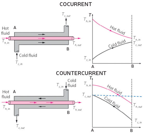
A) Generally, yes. PHE are symmetric in case of same number of passes (1/1, 2/2 etc.) and major part of PHE are single pass. If the mixing arrangement of plate pack is not identical, different pressure drops could be possible. Of course, inlet and outlet position must be changed for both fluids, otherwise counter-current arrangement would be co-current with different performance. Just in case of dirty fluid with particles (i.e. Nile river water), it is recommended to have
the inlet on the bottom side so that particles will precipitate and clean water can flow up in the channel – See Fig. 3.

Q5) The manufacturer offered a PHE with connections size smaller than my piping. Why?
A) The selection of connection size is used a parameter nozzle velocity with water 5.5 m/s. A major part of PHE design software switches to larger size if it is higher. Standard velocity in piping is 2-2.5 m/s so that the size of connections is normally smaller and conic reduction is often reduced.
Q6) Data sheets mention that PHEs must have a “U” stamp. What does that mean?
A) The typical requirement for Pressure Vessel Code in oil & gas applications is ASME VIII Div.1
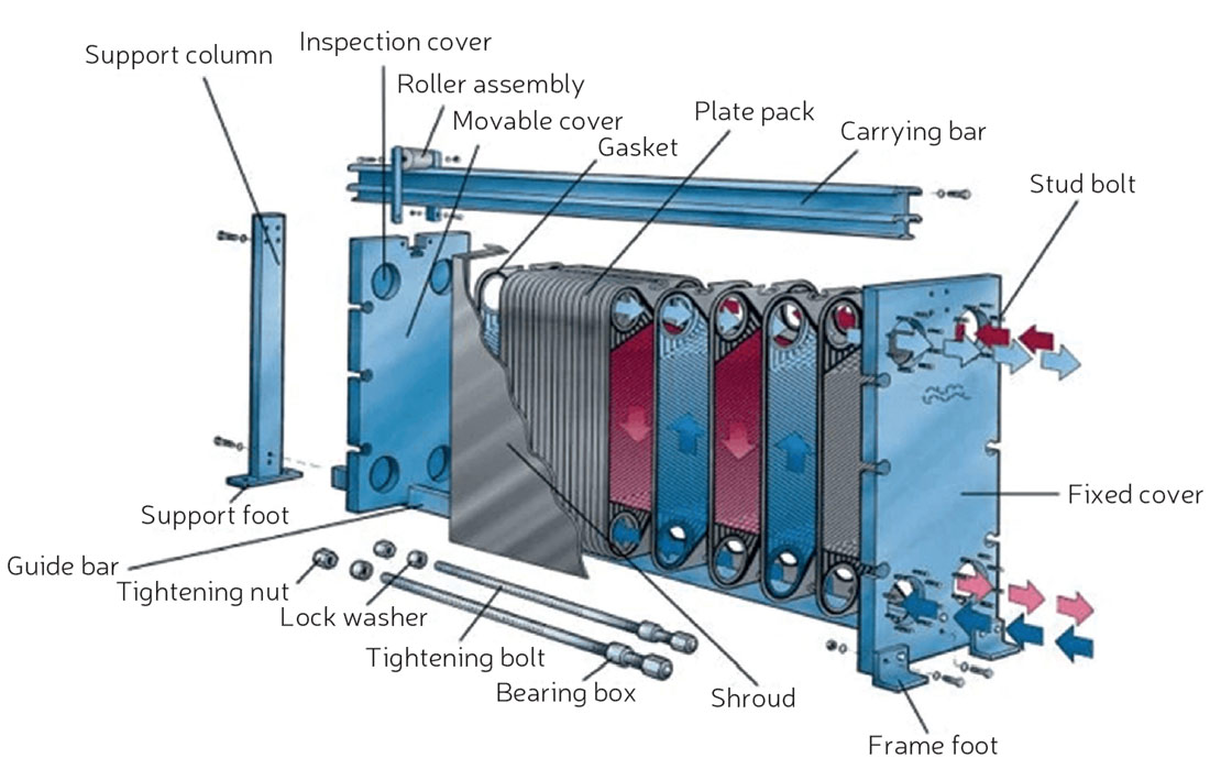
with a U stamp and nozzle load calculation according to API 662 table 2 severe conditions. A PHE is considered a pressure vessel with flat covers and the calculation is on tightening bolts on the frame and mobile cover. In PHE design, this includes extra costs for material (SA-516 Gr.70 for frame, SA-193 Gr.B7 for bolts, SA-192 Gr.H2 for nuts etc.). The manufacturer must be a U stamp holder (or frames should be manufactured by a pressure vessel subcontractor with workshop
U approved). Sometimes it is acceptable “according to ASME VIII Div.1 without U stamp” to get proper material with right stress calculation (i.e. frame thickness).
Q7) My fluids are dirty, with fibres and particles. Can I use a PHE?
A) Of course, it depends on the size of particles. In the past tube-in-tube heat exchangers or spiral heat exchangers were commonly used. Recently, the channel size of special plate named “Freeflow” with 12 mm wide gap opened several applications like ethanol plants. Furthermore, in cases handling non-Newtonian fl uid (i.e. sauces, ice cream), PHEs performed better. In some cases, such as in the textile industry, a Bernoulli filter was installed upstream of the PHE.

Q8) I have three PHE offers with three different heat transfer areas and, therefore, three different prices. What should I do?
A) Technical alignment is sometimes difficult on PHEs. Evaluation must take care of several factors. General criteria should ensure comparing apples with apples and not apples with oranges.
Check if pressure drops are correct, if FF (or surface margin) are indicated, if physical data are correct (i.e. lubricant oil ISO VG64 is mentioned but data are of ISO VG32), if connections are rubber lined when data sheets mentioned metal lined, if in QCP checks are mentioned according to specs etc. At the end of the day, a cheaper supplier could create issues after PO.
Q9) PHE design temperature is 180°C, but I know that Tmax in operation will be 140°C. Should I mention this to the PHE supplier?
A) Yes, gasket selection will be according to design temperature. Wide range of gasket materials is available Viton FKM, Afl as 150, TFE/P, EPDM, Buna-n, Silicone, NBR etc. If you are in trouble don’t hesitate to select a semi-welded SPHE or a fully welded WPHE.
Q10) A PHE manufacturer mentioned thermal length. What does this mean?
A) Thermal length is a dimensionless number that allows the design engineer to relate the performance characteristics of a channel geometry to those of a duty requirement.
Thermal length (theta) is the relationship between temperature difference DT on one fluid side and LMTD. The thermal length of a channel describes the ability of the channel to affect a temperature change based on the log mean temperature difference (LMTD).
 The thermal length of a channel is a function of the chan-nel hydraulic diameter, plate length, and the angle of the corrugations, along with the physical properties of the process fl uids and available pressure drop (see Fig.5).
To properly design a PHE, the thermal length required by the duty must be matched with that achievable by the selected channel geometry.
A PHE is said to be optimally sized, if the thermal length required by the duty can match the characteristics of the channel, by utilizing all the available pressure drop with no over-dimensioning, for any chosen channel geometry.

ABOUT THE AUTHOR
 Dr. Giuseppe Tommasone is a heat transfer expert and consultant for an EPC contractor. His
expertise is in special heat exchangers in the oil & gas industry where he helps customers to improve performance by providing heat transfer solutions.
Since 1979 he has worked with and helped more than 3000 small, medium, and large businesses in the oil & gas, power, steelworks, chemicals, and pharma industries as well as EPC contractors.
Dr. Tommasone studied Chemical Engineering in Milan, Italy.
This article is part one of a two-part series. The second Q&A session will appear in the July/August issue of Heat Exchanger World magazine.


