
A heat exchanger is a device that is used to transfer heat between a process and a cooling fluid during an industrial application. The term “thermal management” best describes the heat exchanger function. Relatively simplistic in design, HE’s operational condition can significantly impact the day-to-day energy consumption of an industrial process and its carbon footprint. Due to phenomena such as biological fouling (aka, biofilms), calcium carbonate deposits (aka, scaling) & corrosion, cause heat exchangers to increase GHG emissions and energy expenditures.
By Robert B. Bender BS, MBA, MPTD

Heat exchangers are basic devices found in large numbers in all industries including mining, chemical production, petroleum refining, metallurgical, power generation and large commercial facilities (educational, multi-unit dwellings, manufacturing, warehousing, etc.). Typically rugged, they are over designed to compensate for potential inefficiencies to minimize excessive downtime or diminished functionality. Exchanger parameters to be considered for optimum function are exchanger size, plate surface area and importantly, cooling water flow characteristics. Unfortunately, even though sufficient design margins are anticipated, certain conditions, such as cooling water fouling (as seen in Figure1), can result in increased energy draw and thus excessive GHG. The results of this degrading functionality are expressed through reduced heat transference and increased back pressure within the cooling water system. For a heat exchanger to function efficiently, it requires clean heat transfer surfaces and unimpeded cooling water flow. Fouling occurs when contaminants within the cooling water adhere and solidify on heat transfer surfaces and in flow spaces. This condition begins immediately after a clean heat exchanger is brought online. Although not immediately apparent, as formations increase in density or dimension, there is an ever-decreasing function expressed by the exchanger. Each exchanger requires a specified cooling water volume, speed, and pressure to ensure heat extraction. This is not achieved if there is impeded flow space or misdirection away from heat transfer surfaces. Obstructions reduce flow volume which causes increased back pressure across the exchanger.
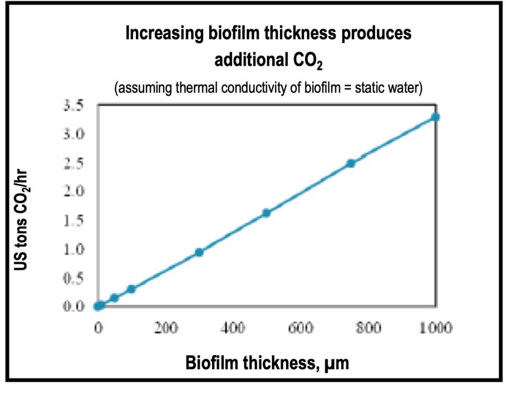
Furthermore, on heat transfer surfaces, the biofilms & scaling function as thermal insulators, reducing the transfer of heat from one fluid to another. Sensors will demand greater water flow from the cooling water pump as a response to a temperature and pressure rise. To compensate, the pump increases water output necessitating increased amperage draw. This increased energy is typically from a source that uses fossil fuel combustion for electrical energy production, ergo the need for more fossil fuels, and their negative impact on our environment. Even a small, incremental rise in pump demand due to foul formation can often translate to measurable increases in GHG generation (see Figure 1). There is an ever-increasing decline in function (and corresponding increase in energy draw) that continues until an acute condition, such as total malfunction, requires an emergency disassembly. Unfortunately, due to the importance of a heat exchanger within a process system, they are not readily taken offline to clean and are typically tolerated until and when an issue arises.
Figure 1 is from one of the many papers that have indicated the relationship between heat exchanger fouling and its environmental impact [3,4]. The paper concluded the following: “…the presence of unwanted deposits on heat transfer surfaces in power station steam condensers can increase the discharge of greenhouse gases. The extent of the increase is of course dependent upon the thickness of the deposit. The loss of heat recovery and the additional energy for pumping represent a loss of thermal efficiency. When fuel combustion supplies energy, additional greenhouse gas emission will result.”
Technical edification of quantum mechanics
An QMT Collar water treatment devices use quantum technology, an emerging, yet proven technology, to keep Heat Exchangers and other industrial equipment operating at peak efficiency. The QMT Collar uses specially modulated ultra-fine waves, stably stored on a silicon-aluminum material by utilizing laser injection technology. The QMT Collar continuously emits pre-recorded ultra-fine vibration waves, interfering with the material waves of various substances (Biofilms, Iron Oxide, Calcium Carbonate et.al) that results in a coordinated resonance reaction that causes physical changes that eliminate forming, bonding and sedimentation. The microscopic appearance of the substances will exist in the form of particles which will be flushed away by the circulating water. They will not accumulate on the Heat Exchanger Plates or Tubing. Any fouling or bonding that does exist will be broken down and flushed out as suspended solids or in solution.
The QMT Collar water treatment products use quantum mechanics technology. This technology is the latest generation of environmentally friendly water treatment technology developed based on quantum mechanics. It uses specially modulated electromagnetic waves to interact with a dielectric material made of a special alloy composed of silicon and aluminum and stably stores ultra-fine vibration waves on this dielectric material by utilizing laser injection technology. The dielectric material will continuously emit pre-recorded ultra-fine vibration waves, changing the material waves of various substances in the medium through the medium (such as water, oil), resulting in a coordinated resonance reaction, causing physical changes, that is, changing existence. Form, no bonding, no sedimentation. The macroscopic appearance is calcium carbonate, and iron oxide will exist in the form of particles, which can flow away with the circulating water without accumulating on the pipe wall. Organic matter such as bacteria and algae will die in the shock wave environment, achieving the function of inhibiting bacteria and algae.
Mechanism of action scale inhibition & removal
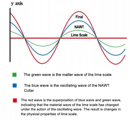
There are a large number of soluble salts in the circulating water system, mainly Ca(HCO3)2. As water temperature and other conditions change, unstable calcium bicarbonate decomposes into the inorganic compound calcium carbonate (CaCO3), which is extremely insoluble in water. A single calcium carbonate molecule which has a weak charge polarity on a microscopic level and is easily affected by water or other charged substances will aggregate and grow into flaky or even massive mixed crystal structures on the pipe wall or Heat Exchanger Plate. These mixed crystals are arranged in a staggered pattern to form an extremely strong scale layer that requires the use of chemical acids or high-energy physical impact to peel it off. Under the influence of an QMT water treatment product, single or small clusters of calcium carbonate molecular crystals in the aqueous solution are disrupted by the cooperative resonance effect of ultra-fine vibration waves. The microstructure of calcium carbonate crystals changes from a needle-like structure that is easily cross-bonded to a spherical or small granular structure with a smoother appearance. That is, scale appears as loose small particles that no longer adhere to the inner wall of equipment or pipes. It settles in the form of soft floc at the bottom of the container in still water and is eventually carried away by the water flow. When the calcium ion concentration reaches 400 mg/L and the pH value exceeds 11, it still shows good anti-scaling effect.
Corrosion prevention & inhibition
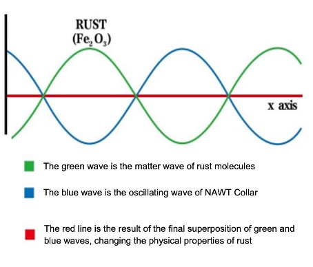
During the operation of the industrial circulation cooling process, there is a layer of metal oxide on the surface of the equipment and pipes .The ultra-fine vibration waves generated by products using quantum mechanics technology can react on iron atoms on the metal surface and oxygen atoms in the water, causing the iron atoms and oxygen atoms to be directionally combined to form a Fe3O4 film that acts on the inner wall of the pipeline, thereby isolating the erosion of corrosion factors. This oxide film is denser and has better corrosion inhibition performance when subjected to high-chlorine corrosive water.
Bacteria & algae
Quantum Technology products can continuously release ultra-fine vibration waves similar to biological signals into the water. After the water environment is affected, it destroys the biofilm, the nutritional source of bacteria and algae, making them unable to survive. At the same time, under the action of ultra-fine vibration waves, bacteria and other pathogen fragments are disintegrated, the biofilm loses viscosity and is dispersed in the water and finally discharged through the sewage system.
Benefits of quantum mechanics technology in heat exchangers
No maintenance required
Other types of mechanical systems used to mitigate bio-fouling & scaling in heat exchangers i.e., nanobubbles, magnets, UV, require additional equipment, equipment that requires maintenance ergo additional costs are accrued. Quantum Mechanic Technology requires no maintenance. The human element is removed. Install it & forget it!
No energy source required
Nanobubbles, UV, Magnets require a power source. It increases electricity costs and increases installation costs.
No chemicals needed
Eliminates the costs of procuring chemicals, handling chemicals, disposing of chemical containers and special handling equipment. Keeps the chemicals out of the environment. Biofilms can now be 100% removed, chemicals cannot remove 100%.
Easy, non-invasive installation
No cutting pipes, no installing flanges, no welding. Only two bolts that need tightening with only one tool, an Allen Wrench. No lost production and no downtime for equipment. The QMT Collar works on any material used for piping: steel, cast steel, stainless steel, cast iron, ductile iron, copper, PVC, CPVC, composite et.al. The pipe gets wrapped with RED electrical tape to prevent any galvanic reaction. Red tape needs to be used, because black is not conducive to the transmission of the waves. The red-light wave has a longer wavelength, so it is more conducive to spectrum transmission and can effectively penetrate the atmosphere and water, while black does not represent a specific wavelength, so the transmission ability is weaker. Depending on size, it should not take longer than 30 minutes. No Special Skills required to install. No footprint installs on the OD of an existing pipe.


Advanced solid-state technology
Activated upon installation. Useful life of over 10 years. Not affected by ambient conditions, heat, cold, water spray, high humidity, high temperature, VOC’s, will not affect performance.
Extends life of service equipment
Inhibits & removes scale so cooling water flows unimpeded. No increase in pump motor speed or amperage draw. Keeps valves fully operational and cuts corrosion in piping systems.
Saves energy
No energy source required, no increased energy required to overcome flow impediments. Reduces system operating cost. For decades, industry has borne the financial expense and challenges presented by heat exchanger fouling because of the difficulty of remediation or prevention. It was understood that there was a fiscal impact of maintenance, repair, excessive energy, and loss of process which could reach .25% of an industrialized country’s GNP due to fouling [5]. These challenges were tolerated since the results of these inefficiencies were only felt by the facility. It was the advent of climate change and an understanding that each malfunctioning heat exchanger offers a compounding impact on environmental global events. It is now universally accepted that there is a need to reduce GHG expression from industrial process systems by utilizing a sustained method to prevent fouling in heat exchangers.
About the Author

Robert B. Bender BS, MBA, MPTD has been introducing emerging technologies to corporate America for over half a century. His clients include Ford Motor Company, General Motors, Anheuser-Busch, National Grid, Brookhaven National Labs, Department of Environmental Protection – New York City, US Steel, Bethlehem Steel, Lever Brothers, AMTRAK, Long Island Railroad et.al. Mr. Bender’s creative problem-solving skills at all corporate levels have resulted in much lower costs for the maintenance, operating and procurement corporate functions. Has made it his life’s quest to remove toxic chemicals from the environment. Sits on the executive boards for DPCC, LIMBA, and AFE (Association for Facilities Engineering). President of the Long Island, NY Chapter of AFE since 2007.
Acknowledgments:
- Manabe S (2019) Role of greenhouse gas in climate change. Tellus A: Dynamic Meteorology and Oceanography 71: 1-13.
- Mohammed Ouikhalfan, Omar Lakbita, Achraf Delhali, Ayalew H Assen, Youssef Belmabkhout (2022) Toward Net-Zero Emission Fertilizers Industry: Greenhouse Gas Emission Analyses and Decarbonization Solutions. Energy Fuels 36: 4198-4223.
- Casanueva Robles T, Bott TR (2005) The environmental effect of heat exchanger fouling: A case study. ECI Symp Ser, Kloster Irsee, Germany RP2: 278-282.
- Müller-Steinhagen H, Malayeri MR, Watkinson AP (2009) Heat exchanger fouling: Environmental impacts. Heat Transfer Eng 30: 773-776.
- Müller Steinhagen H, Malayeri MR, Watkinson AP (2005) Fouling of Heat Exchangers-New Approaches to Solve an Old Problem. Heat Transfer Engineering 26: 1-4. Special acknowledgment to Michael Radicone “Thank you for your inspiration.”
About this Technical Story
This Technical Story was first published in Heat Exchanger World Magazine in March 2025. To read more Technical Stories and many other articles, subscribe to our print magazine.
Technical Stories are regularly shared with our Heat Exchanger World community. Join us and share your own Technical Story on Heat Exchanger World online and in print.