As the capacity of green hydrogen production plants increases to multi 100 MW, managing the resulting waste heat becomes a critical challenge. Huge amounts of waste heat occur and must be properly removed from the process and, unless it has no further use, be emitted to the ambient air. Temperature differences are low, and the cooling system design needs sensitive attention. A one-size-fits-all cooling concept doesn’t work. Instead, each project demands a tailored approach. This article explores how to identify the best-fitting ambient air-based cooling solution, with a special focus on Kelvion’s cascade cooling system – an intelligent, central cooling concept designed for efficiency, flexibility, and early integration into plant planning.
Alexander Gernhardt, Senior Application Engineer Green Technologies, Kelvion
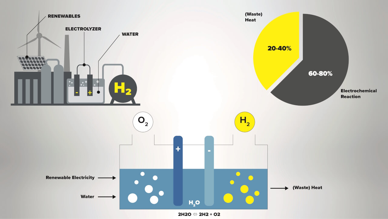
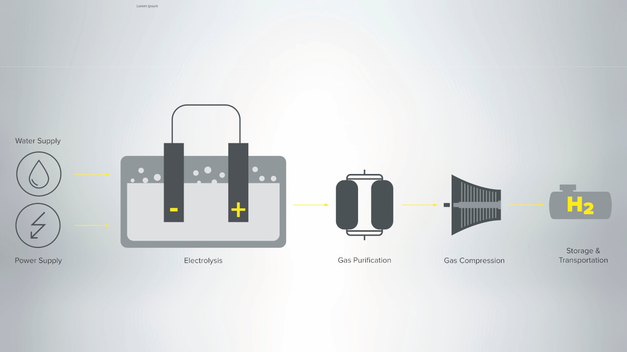
Green hydrogen is produced from renewable energy by the electrolysis process. This means using an electric current to split water molecules into hydrogen and oxygen. Alkaline electrolysis (AWE) and Proton Exchange Membrane electrolysis (PEM) are among the major technologies for producing green hydrogen.
However, these systems have just a 60-80% efficiency rate, which represents the level of electrical energy that will be transformed into hydrogen. The remaining 20-40% becomes heat that can either be recovered and reused in, for example district heating, or emitted into the ambient. This means that an electrolyzer system with 100 MW installed capacity will transform around 20-40 MW of the electrical energy supplied to the process into heat.
To ensure that the electrolysis occurs in stable and efficient conditions, it is therefore essential that all plant equipment interacting with the process, especially the heat exchangers, are carefully chosen and designed.
The biggest share of the waste heat is emitted by the stacks themselves, but other sub-systems, like the power supply, the purification system and the compressor also emit waste heat that must be removed.
If the waste heat is not reused, a central cooling system is essential.
A water-based system is a good option if a river or an ocean is nearby and cooling by this is allowed. If no water-based heat sink is available, an ambient air-based cooling system is the obvious choice.
Dry, adiabatic or wet cooling system
An ambient air-based cooling system can in general be executed as dry, adiabatic or wet type.
In a dry cooling system air coolers are used. The cooling media, mostly a water-glycol mixture, flows within the tubes and is cooled by the ambient air.
A temperature approach of minimum approx. 5 K in relation to the dry bulb temperature should be present for a dry cooling system to make sense.
In cases where the ambient air conditions are high and pure dry cooling cannot be realized, the air coolers can be equipped with an adiabatic system in the form of a spray, pad or hybrid system. Depending on the size of the plant and the amount of waste heat there are two directions to consider – dry, adiabatic or hybrid cooling based on V-type standard coolers up to a thermal duty of approx. 50 MW. If the thermal duty exceeds 50 MW it can make sense to use Air Cooled Heat Exchangers (ACHE) as the cooling system, being by nature more customized, using bigger fans, a steel structure beneath and, if needed, fulfilling higher requirements like API 661. If enough water for cooling purposes is available, a purely wet cooling system by means of a cooling tower is the right choice.
In general, a pure dry cooling system has the biggest footprint and highest electrical consumption whilst a pure wet system has the smallest footprint, but the highest water consumption.
Regarding heat exchange solutions in an electrolyzer system, the ambient air-based cooling system has, in most cases, the highest CAPEX share in relation to the required heat exchanger equipment for the electrolyzer plant. Furthermore, temperature levels in PEM and AWE are moderate in the range of 60 – 80°C. Depending on the ambient conditions, the temperature difference to the ambient air temperature can be very small.
It is therefore hugely important to follow an holistic approach when designing the thermal management of the plant. This means optimizing the different heat exchangers and temperature levels to each other to achieve the most efficient setup.
When investigating and designing the central re-cooling system, all factors that are relevant for its design must be taken into account to come up with the best system setup.
The factors to consider for the central cooling system are manifold and include:
- Ambient conditions like dry bulb temperature and wet bulb temperature
- Planned CAPEX budget
- Water availability on site
- Allowed sound power/ sound pressure level
- Temperature levels and thermal duties of the sub-systems
- Electrical consumption and OPEX
- Plant location like altitude, pollution, atmosphere
- Available plot size
So, for example, for one project the available footprint can be the dominant driver while for another project the allowed water consumption is dominant.
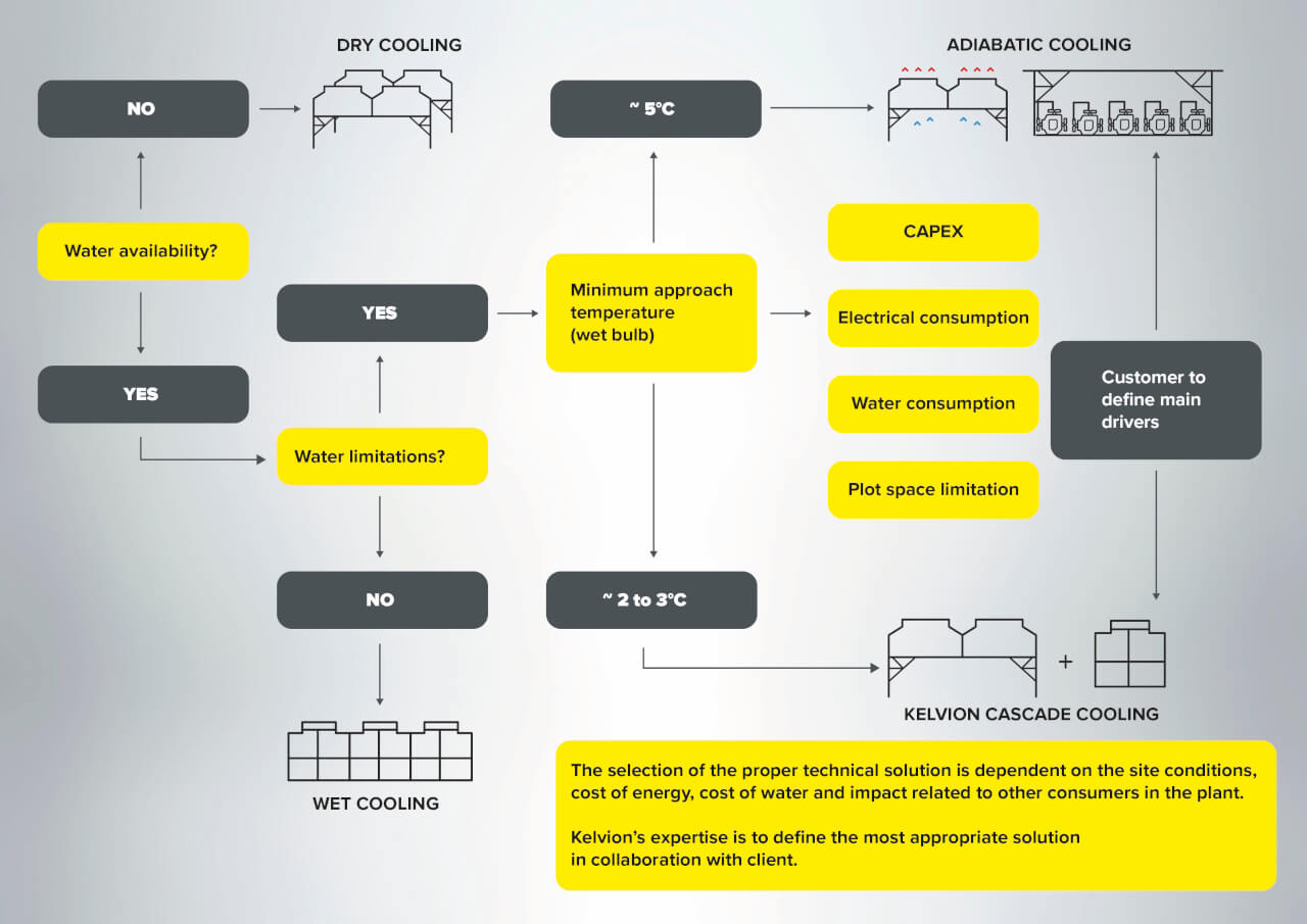
It is therefore recommended to start by identifying the most suitable system. The logic diagram below can help with this.
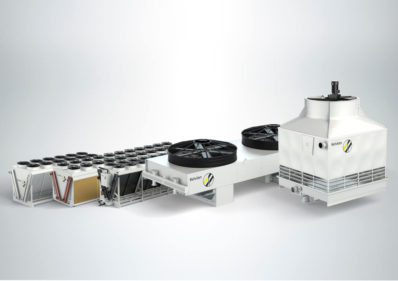
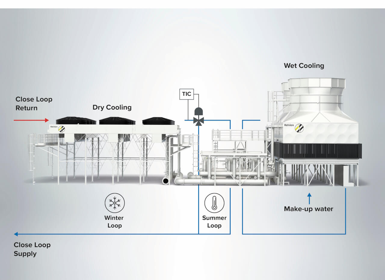
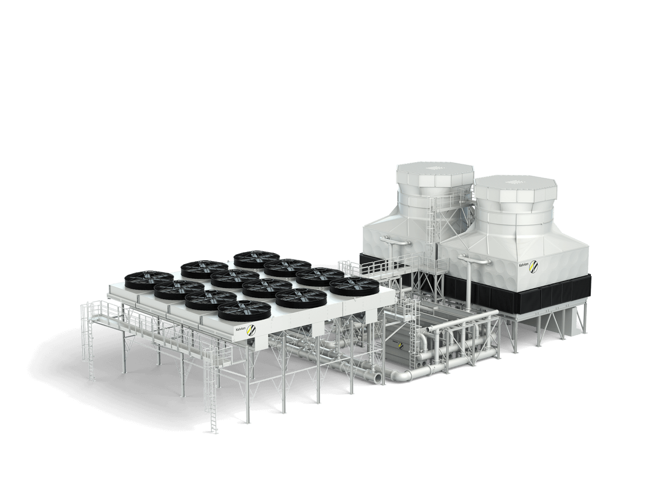
The first question to consider is whether water for cooling is available. If not, then a dry cooling system must be selected. If yes, purely wet or adiabatic system can be used, depending on if the cooling water amount is restricted/ limited. If not, most probably a wet cooling tower is the best choice. If it is restricted, the next question is which temperature difference to the wet bulb temperature is given. If the temperature difference is around 5 K, an adiabatic system can be realized. If the temperature difference is even lower, the Kelvion cascade cooling system can be the right choice. The cascade cooling system is a combination of a dry cooling and a wet cooling system. It consists of dry air fin coolers and wet cooling towers that are combined via a plate heat exchanger pump skid.
Here’s how it works:
During colder conditions, meaning when air ambient temperature is sufficiently lower than the outlet process fluid temperature to be cooled, the system runs only as a closed loop within the ACHE. This enables the size of the equipment to be kept to a minimum and especially the quantity of motors driving the fans. The motors are running under variable frequency drives, affording the lowest energy consumption possible.
In warmer conditions, the ACHE run at 100% capacity and the additional cooling is then provided by the wet cooling tower. Running in a closed loop with a plate heat exchanger, it provides the necessary cooling capacity to lower the outlet process temperature further. This means that the water consumption throughout the year is as low as possible.
This cascade cooling system is a smart solution, combining both advantages of a dry and a wet cooling system, thus lowering energy and water consumption and optimizing CAPEX and OPEX. Another advantage is that the cooling water quality can be lower than in the case of an adiabatic system, or even sea water can be used.
Conclusion
There are many different possibilities for an ambient air-based cooling system in large green hydrogen electrolyzer plants. There is no best uniform ambient cooling solution available but to achieve the most suitable cooling solution, various factors need to be evaluated per individual project and often case studies are needed to identify the most appropriate one. Kelvion’s approach is to get involved in the early stages of the project and advise customers on a tailored, holistic solution for the thermal management system of their plant.
 About the author
Alexander Gernhardt has 14 years of experience in heat exchangers, having had positions in R&D, product management and is currently Senior Application Engineer Green Technologies within Kelvion.
About this Technical Story
This Technical Story was first published in Heat Exchanger World Magazine in July 2025. To read more Technical Stories and many other articles, subscribe to our print magazine.
Technical Stories are regularly shared with our Heat Exchanger World community. Join us and share your own Technical Story on Heat Exchanger World online and in print.


 About the author