

Central cooling systems for large-scale green hydrogen production can be based on wet or dry cooling. Alternatively, hybrid solutions are available as well. This article discusses three such solutions and considers the factors influencing the selection of cooling technology.
By Roy Niekerk, Director Global Sales & Solutions Hydrogen, and Radhouene Manita, Application Engineer, Kelvion Thermal Solutions
The two most established processes for green hydrogen production are alkaline water electrolysis and polymer electrolyte membrane (PEM) electrolysis. In both processes, a liquid is recirculated over an electrolyser stack to form hydrogen and oxygen. During the electrolysis process, heat is released, which needs to be cooled away. This cooling step is normally done in a plate and frame heat exchanger. However, more cooling positions in the hydrogen production process are available. Alternating current electricity is changed into direct current, which releases heat. Two further positions are the formed oxygen and hydrogen, which are cooled before further purification. The deeper the cooling, the more water is ‘knocked out’ by means of condensation, reducing the required size of the drying section in the plant. Further downstream, the hydrogen is compressed, which requires compression interstage and aftercoolers. A closed loop of water or water-glycol mixture is used to cool all the different coolers in the hydrogen production process. And the closed loop is cooled in a central system. Electrolyser capacity is normally expressed in megawatts. And as a rule of thumb, roughly 25–30% of that capacity is cooled away in the central cooling system. Different cooling methods exist.
Dry or wet cooling
Air Fin Coolers (AFC) are one method of cooling down a closed loop. Typically, an AFC consists of a series of horizontal finned tube bundles with box headers at each end that run either underneath or above axial fans within a plenum chamber, which directs the air flow. Usually, the air blows upwards through the tube bundles, cooling the hot liquid. But the fans can be configured to forced or induced draft, depending on whether the air is pushed or pulled through the tube bundle. Large-size industrial AFCs offer a great design freedom in terms of plot configurations, header types, and project specifications that need to be followed. A big advantage is that no water is used. As a rule of thumb, the temperature approach in an AFC is 10°C. By using special tube technologies such as Groovy-Fin® and DIESTA®, the temperature approach can in some cases be pushed to 7°C, but it is not advisable to use such low values in the initial project development.
As an example, if a project designs the system for maximum 30°C dry-bulb temperature and Groovy fins are used with 7°C approach temperature, the closed loop can be cooled down to 37°C as a minimum. Temperature approach in a plate and frame exchanger is 2°C. The resulting mini-mum process temperature is therefore 39°C.
In regions where water is available, however, open cooling towers can be selected. Water that is sprayed down in the tower is brought in contact with air, which is pulled through the tower fill material by means of a large fan-motor combination. A very small portion of water is evaporated, causing the remaining water to cool down. A big advantage of a cooling tower are the much lower temperatures it can reach compared to dry cooling. In the above-given example, a dry-bulb temperature of 30°C was assumed, which is a typical value for Western European locations. In such locations, however, the wet-bulb temperature can be as low as 21°C. A rule of thumb for cooling towers is a 4°C approach to wet-bulb temperature. In this case, the cooling water can be cooled down to 25°C. An approach of 2°C must be added for the closed loop as a plate and frame heat exchanger is used to transfer heat from the closed loop to the open cooling tower. The closed loop is cooled down to 27°C. However, another 2°C must be added for the plate and frame exchanger in the process. This results in a minimum achievable process temperature of 29°C.


Fogging system
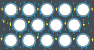
The highest ambient temperatures normally occur only over a relatively short period of time each year (except for tropical regions). Nevertheless, this design point determines the overall size of the AFC. And this results in an installation that is oversized most of the time. A clever solution to this problem is the use of a fogging system. Hundreds of small nozzles are installed below the AFC tube bundle. Very pure water (demineralised-water quality or at least soft water with inlet pressure between 3 and 5 bars) is atomised and sprayed into the air stream, evaporating before it enters the tube bundle. While the water evaporates, it cools down the air before entering the tube bundle. This principle is called adiabatic cooling.
By using a fogging system, the inlet air temperature can be reduced by as much as 10°C! Such a reduction in design ambient air temperature has a dramatic impact on the size of the AFC. Because ultra-pure water is used and has evaporated before entering the bundle, there are no issues with corrosion or fouling. Kelvion Thermal Solution provides these systems, including the pump skid and process control, to ensure proper humidification. As part of the detailed thermal design, data is provided about the water usage as a function of the ambient temperature. Of course, when the temperature gets below the design ambient air temperature, no water is used at all.
So, when could the use of a fogging system be beneficial? Fogging is efficient for ambient temperatures above 25°C and humidity below 70%. It is meant to be used during the hot season, at the hottest hours of the day when humidity is low.


Adiabatic pads
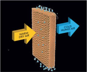
Ambient air passing through the wetted adiabatic pad increases in relative humidity, cooling the entering air’s dry-bulb temperature towards the entering air’s wet-bulb temperature. The lower dry-bulb temperature exiting the adiabatic pad is referred to as the depressed dry bulb. In an adiabatic fluid cooler, the pre-cooled air with the depressed dry bulb travels through the tube and fin, offering a substantial increase in heat rejection capability.
A pad system is often used in cases where the relative humidity is lower (‘dry’ air) at higher ambient air temperatures.
The main requirements to install an adiabatic pad system are:
• Inlet water hardness limit
• Inlet water conductivity limit


Technology Comparison
In the paragraphs above, some of the factors influencing the selection of cooling technology have been discussed, such as availability of water and achievable process temperatures. How to compare these technologies therefore depends a lot on the project requirements. In Table 1, the four different technologies are compared, with the minimum achievable process temperature set at 39°C for the three technologies employing AFC. Since generally achievable temperatures are a lot lower in cooling towers, minimal process temperature is set at 29°C for the cooling tower option. The picture will be different when the minimum achievable process temperature is an important factor for the project. This could be the case, for instance, when cooling down the produced hydrogen has a significant impact on the sizing of the drying section. Table 2 provides a comparison of the four technologies in a scenario where the project is aiming at the lowest possible process temperature.
Tundracel cooling tower
Some projects would benefit from a cooling tower, but the water available is of insufficient quality. In such cases, the Tundracel cooling tower is one solution. The Tundracel is a closed-loop cooling tower. The product to be cooled (closed-loop cooling water for green hydrogen plants) is led through U-tube bundles. The tubes are sprayed from the top with water. In co-current flow, air is sucked in through the bundle by means of the fan next to the bundle.
While water and air flow through the tube bundle, the water evaporates, causing the water film on the tubes to cool down. Below the bundle, the water drops in the water basin, from where it is pumped back to the top to be sprayed over the tube bundle. The air turns to the second part of the tower and flows upwards, through the fan. The air velocities in the turning section and in the second part of the tower are designed in such a way that any droplets will drop back into the water basin.
Because air and water flow downwards together (co-current flow), the air helps to spread water evenly over the entire tube surface. There will be no dry spots, resulting in less scaling and fouling.
The Tundracel is therefore suitable for poor water qualities, such as:
• Blowdown from cooling towers and boilers
• Waste streams from demineralizers, scrubbers, etc.
• Plant effluent wastewater
• Brackish water
Conclusion
Thermal management in green hydrogen plants can be divided into two extremes: dry cooling and wet cooling. In general, it can be said that dry cooling is characterised by higher power consumption and larger footprint than wet cooling towers but of course no water consumption.
However, between these two extremes, there is a whole world of intermediate, or hybrid solutions. Fogging systems and adiabatic pads systems for Air Fin Coolers and the Tundracel closed-loop cooling tower are just some of them. The best choice highly de-pends on the project requirements, such as availability of water, water quality, and site conditions (dusty and/or windy).
About the company
Kelvion Thermal Solutions (KTS) is an expert in heat exchange. KTS normally gets involved in early engineering phases of large projects to help clients in making such technology choices.
About this Featured Story
This Featured Story was first published in Heat Exchanger World Magazine in November 2022. To read more Featured Stories and many other articles, subscribe to our print magazine.
Featured Stories are regularly shared with our Heat Exchanger World community. Join us and share your own Featured Story on Heat Exchanger World online and in print.