The application of coatings with amorphous carbon films, also called Diamond-Like Carbon (DLC) in heat exchangers has already been shown to substantially reduce fouling. However, their wide application, especially with regard to shell and tube heat exchangers, has not occurred to date. Researchers at the University of Applied Sciences Upper Austria, Wels, Austria, promote industrial applications of DLC, using the PACVD reactor technology of the RUBIG Group.
By Albert Angerbauer a, Richard Gangl b,a, Michael Malfentc a, Christian Forsich a & Daniel Heim a
a University of Applied Sciences Upper Austria, Wels, Austria
b Brückner Textile Technologies GmbH & Co. KG, Tittmoning, Germany
c Bilfinger Industrial Services GmbH, Linz, Austria
In this article, experiences with welding tests with DLC-coated tubes and appliance parts for a shell and tube heat exchanger (600 mm inner diameter, 5000 mm length, 200 pipes with 25 mm outer diameter) are presented. The welding seams were of good quality. The coatings showed minor ablations near the welding area. It can be stated that apparatus of these dimension can be used with 80 to 90% effective DLC coating, which are capable of withstanding high pressure and resisting temperatures up to 450°C. With improvement in the production of DLC-coated tubes, a 99% ratio has been targeted for the future.
Introduction
Fouling in heat exchangers is of major importance as its generation and growth is dependent on a wide range of parameters. There are installations that do not need to take counter-measures as their typical reserve of heat transfer area has proved to be sufficient. Other installations need to be intensely cleaned on a regular basis, which leads to extra maintenance costs and production loss. Another area of concern regarding fouling is the use of low-temperature energy sources such as waste heat from the process industries. When heat recovery is low additional energy such as natural gas is required, leading to a higher carbon footprint.
There are a number of possible counter-measures to prevent fouling. For example, the setting of more ap-propriate flow rates or the use of various inhibitors are well-known measures. Surface coatings can also be ap-plied. The Institute for Chemical and Thermal Process Engineering and the Fraunhofer Institute for Surface Engineering and Thin Films, both located in Braunsch-weig (Germany), carried out intensive research during the early part of this century on this theme. Geddert and colleagues report the promising use of DLC coat-ings, which are available in a wide range of modifica-tions depending on the source of fouling [Ged07]. In further projects they developed an installation to coat tubes approximately 20 mm in diameter and 2 m in length with DLC coating inside [Aug09]. The effec-tiveness of this approach for industrial applications has been insignificant, as a full PACVD facility has operated for only one piece of tubing. Although there was certainly some scale-up potential, in later projects they tried to coat flat sheets, which were then coated with DLC-type thin layers and rolled into half pipes, which were finally welded to full tubes [Ric17]. They found this methodology more appropriate for industrial applications, and with special modifications to the type of DLC layers, half-pipes of satisfactory quality were produced. The difficulty still present, however, was the stability of the form in the final welding process, as two half-pipes of about 2 m have to be joined within a nar-row tolerance range.
The researchers at the University of Applied Sciences Upper Austria, Wels, Austria were also interested in facilitating the industrial application of DLC to shell and tube heat exchangers, using PACVD-reactor technology of the RUBIG Group, Austria which applies a different technology to the institutes mentioned above [RUB21].
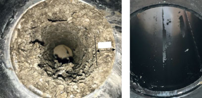
DLC from the Wels laboratories has been proven to be effective in mitigating fouling with magnesium ammonium phosphate (M-A-P, MgNH4PO4, also called struvite) in a major sewage plant using stainless-steel tubes [Kai20]. Fig. 1 gives an impression of the results after five months of operation, as with DLC there was practically no scaling but without coating some 15mm.
The present status of DLC applications for heat exchangers may be summarized as follows:
■ The variant of DLC has a great influence. There are dopings with Si, H, and other atoms, which are effective, or partly effective, based on the fluid and the temperature levels, as well as the cleaning cycle. Engineering on this matter seems to be mandatory for good results.
■ The industrial use of DLC is mainly present with plate heat exchangers as the coating of flat sur-faces is already well established.
■ Coating inside deep cavities is generally difficult, so longer tubes as typically used in shell and tube heat exchangers cannot be coated inside on an industrial scale.
■ Effective coatings, such as PTFE, are vulnerable to wear and abrasion as well as being limited in the range of their temperature use. DLC would have a clear advantage here in that it is highly resistant to abrasion and durable up to 450°C.
■ In cases where the base material can stand suf-ficient corrosion resistance without coating, there is no need for full protection with a DLC layer. For instance, if the welded zones are not coated, there could be a limited anti-fouling effect of some 10%, but the major benefit in respect to heat transfer would still be in place.
Concept for DLC-type shell and tube exchanger
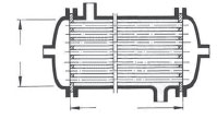
The concept presented is based on the major require-ment of being applicable for high-pressure installa-tions. As a rule they must mandatorily comply with ASME, API, EN13445 or alike. As an example a basic tube-bundle heat exchanger (Fig. 2) was investigated for this paper. It consisted of two base plates with an inner working diameter of 600 mm and 200 tubes of an outer diameter of 25 mm and a wall thickness of 2 mm. The length of the tubes was 5000 mm. The idea was to produce the apparatus in the following stages:
■ The outer shell and the dished floors remained uncoated in this case, so there was no change to standards.
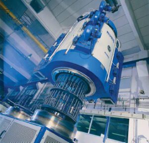
■ The two base plates are manufactured and drilled, then there is a coating in the PACVD reactor of MICROPULS® Diamond Xtended system, RUBIG, thought (Fig. 3) [RUB21]. Their biggest standard machine is DIA 150/240 and offers space for parts of maximum 1.500 mm in diameter and 2.330 mm in length. Depending on the coating required, these dimensions could be adjusted to get the plasma to the right specifications. For the case in question there was enough space to coat the base plates. The drillings can be protected by means of protection hoses, so the question as to whether the drillings should be coated or not is moved to a later analysis and experience. For the further ex-periments it was assumed they were protected, so for the welding tests there was no coating applied on the sides of the base plates.

The tubes for the presented case had a length of 5 m. With a reactor as shown in Fig. 3 it was possible to process pieces of approximately 2 m. It was obviously necessary to join two tubes of 2 m with one of 1 m by means of circumferential seams. Additionally, the production of the tubes had to be challenged, as an L-to-D ratio of 2000/21, which is about 100, was hard to handle without additional means in the reactor to obtain a satisfactory coating inside. The outside coating was standard with this type of reactor and deemed to be proven.
The tubes for the presented case had a length of 5 m. With a reactor as shown in Fig. 3 it was possible to process pieces of approximately 2 m. It was obviously necessary to join two tubes of 2 m with one of 1 m by means of circumferential seams. Additionally, the production of the tubes had to be challenged, as an L-to-D ratio of 2000/21, which is about 100, was hard to handle without additional means in the reactor to obtain a satisfactory coating inside. The outside coating was standard with this type of reactor and deemed to be proven.
Weldings on base plates
Research was carried out with so-called mock-ups. Joining variants in accordance with DIN EN 1708-1 were compared (Fig. 4). The tested tubes were of 25 mm outer diameter and 1, 2, 3 and 4 mm in wall thickness. Tubes of E235 (carbon steel) and 1.4571 (stainless steel) were used. Two types of coatings were applied, DLC and DLC-Si (with silicon doping) with 5–6 µm. To get an impression for the ‘said’ case (Fig. 2), the results of welding 2 mm wall tubes with DLC-Si are discussed in more detail as these combinations are more relevant in industry. In general, the quality of joinings in respect to the weld seam and the porosity and other criteria were completely satisfactory. There were no obstacles
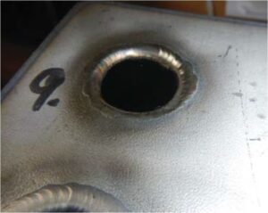
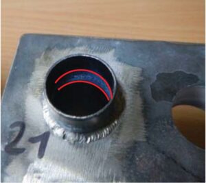
found during welding and in later dye penetrant tests. The first joining variant 1 (Fig. 4) is discussed. With E235 and 1.4571 there was an ablation of the coating around the area of the heat impact (Fig. 5) with about 7 and 5 mm length. It appeared that the wall thickness had a minor impact on this length with the tested dimensions. Variant 2 (Fig. 4) was much better, there was about 1 mm ablation with E235 and none with 1.4571 (Fig. 6). By increasing the wall thickness an increase in the ablation up to 2 mm maximum was noticed. In respect of the present project (Fig. 2) all the tests proved that DLC-type tubes could be used without restrictions.
Circumferential seams
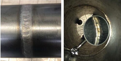
The experiences shown above made it obvious that there would also be an ablation with round seams. The test was carried out using DN80/PN10 tubes with an outer diameter of 88,9 mm (Carbon steel, P235 TR1, 3,2 mm wall; Stainless steel, 1.4301, 4 mm wall). The welding set was MIG with carbon and TIG with stainless. Different variants of V- and I-seams acc. DIN EN ISO 9692 were tested mimicking procedures in shops manufacturing shell and tube heat exchangers. Fig 7 gives an impression of the results. With round seams the standard welding procedure is also not affected by the DLC layer, which was fixed with the mentioned parameters at a thickness of 5-6µm. The most likely reason is that the temperature in the atmosphere of the protection gas of the welder carries enough power to facilitate desorption of the coating before the base material is melted. In this way, the carbon and hydrogen content of the coating disappears with the protecting gas and the melt is not negatively affected. In contrast, the welder reported that it was an easy task as the pipes were very clean. When coating tubes in the reac-tor (Fig. 3), mandatory cleaning prior to coating is obligatory.
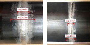
It was surprising that when the tested welding zones were pickled, the visible damaged zones were significantly larger. So the results shown in Fig. 8 are those, which can be expected during operation. The average size of the damaged area was in the range of 20 mm with maxima up to 40 mm on the outer side and 10 to 15 with maxima up to 30 mm at the inner side. Carbon steel did slightly better than stainless steel, but taking the difference in wall thickness of the samples into account, there was no relevant effect found.
Tubes coated inside with DLC
Experiments with the production of tubes which have been coated inside with DLC are at the start-up phase at present, but fabrication steps have already been developed from the experience gained from more than ten years of applying DLC in various industrial areas [For. 14].
The source material is preformed tubes, which have still a longitudinal gap. In practice, there is also an option of using standard tubes and to cut out the weld-ing seam by milling as shown in Fig. 9. The results of the first trials with 400 mm-long samples produced by milling and with shielded ends showed that gaps of about 5 mm are sufficient to obtain a proper inner coating (Fig. 10).


coated with DLC inside and
outside.
The next step is to carry out finishing and longitudinal welding. In trials, conventional welding, as performed with the above-mentioned round seams, is planned, and a similar zone of uncoated surface is expected. A final, but highly important step, is the certification of the procedure by authoritative bodies to get permis-sion to use the tubes in pressurized heat exchangers. This step implies that lessons must be drawn from actions to date. After this, more specific results on the portion of coated heatexchanger area will be sought. It is estimated that it will be possible to achieve some 80 to 90 %, but with advanced welding of the longitudinal and circumferential joint – for example with laser-technology – even up to a 99%-coating ratio may be possible.
For the researchers at the University of Applied Sciences Upper Austria, Wels, Austria, the goal is the realization of the project and gaining feedback from a real case study in order to gain more practi-cal knowledge and to learn more about the beneficial relationships in terms of fouling mitigation in shell and tube heat exchangers operating in the process industries.
Acknowledgements
Proofreading by P. Orgill is gratefully acknowledged.
If you would like to contact the authors, please email your questions and comments to: albert.angerbauer@fh-ooe.at
References:
[Aug09] W. Augustin, I. Bialuch, „Schlussbericht IGF-06/01 – Verbesserung des Fouling- und Reinigungs-verhaltens wärmeübertragender Flächen durch optimierte Oberflächenbeschichtung (Fortsetzungsantrag)“ [Online]. Available: https://www.efds.org/wp-content/uploads/2016/05/IGF-06-01-Schlussbericht.pdf [Accessed 05-09-2021]
[For14] C. Forsich, C. Dipolt, D. Heim, T. Mueller, A. Gebeshuber, R. Holecek and C. Lugmair, “Potential of thick a-C:H:Si fi lms as substitute for chromium plating,” Surface & Coatings Technology 241 (2014) pp. 86–92
[Ged07] T. Geddert, I. Bialuch, W. Augustin and S.Scholl, “Extending the induction period of crystallization fouling through surface coating,” 7th International Conference on Heat Exchanger Fouling and Cleaning -Challenges and Opportunities, Tomar, Portugal, July 1 – 6, 2007
[Kai20] J. Kaissl, A. Angerbauer, D. Heim, C. Forsich, “Prevention of M-A-P-fouling using DLC in a sewage treatment plant”, 16th Minisymposium Verfahrenstechnik und 7th Partikelforum, TU Wien, September 21th-22th, 2020
[Ric17] K. Richter, R. Müller, D. Landgrebe, K. Siedbeneck, W. Augustin and S.Scholl, “Innenbeschichtete Rohre: Ein erfolgversprechender Lösungsansatz zur Verminderung von Foulingeffekten,” 10th Expert conference on roll forming (Fachtagung Walzprofilieren), Darmstadt, Germany, February 20th, 2017
[RUB21] RUBIG Group, “Top of Nitriding and Coating – Nitriding and Coating Furnaces,” [Online]. https://www.rubig.com/fileadmin/user_upload/AT/Downloads/AT_Folder_A4_EN_20210504_digital.pdf [Accessed 08-09-2021]
About this Featured Story
This Featured Story was first published in the November 2021 issue of Heat Echanger World Magazine. To read more Featured Stories and many other articles, subscribe to our print magazine.
Featured Stories are regularly shared with our Heat Exchanger World community. Join us and share your own Featured Story on Heat Exchanger World online and in print.
Featured Story by Albert Angerbauer, Richard Gangl, Michael Malfent, Christian Forsich and Daniel Heim


