
The use of DLC-type coatings for mitigating fouling in shell and tube heat exchangers has substantial potential as DLC is highly resistant to abrasion and known for easy cleaning and minimum fouling. The use in this field was hindered by the lack of effective production procedures. Research at University of Applied Sciences Upper Austria, Wels, Austria (FH OOE) focuses on industrial application of DLC with heat exchangers, using PACVD-reactor technology of RUBIG Group, Austria.
By Albert Angerbauer1, Stefan Mann1, Christian Übleis2, Bruno Petter3, Manuel Schachinger1, Christian Forsich1, Daniel Heim1, 1FH OOE, University of Applied Sciences Upper Austria, Wels Campus; 2Rübig Härtetechnik, Wels, Austria; 3Polysoude Austria, Admont, Austria

There are two production routes in question: G-route gap-coating for long tubes and C-route cavity coating for shorter single-tube pieces. The G-route gap-coating process for long tubes has an inner coating applied via a slit of approximately 2 mm. As the coating is fine and evenly distributed, so-called engineered DLC-type surfaces can be produced. The challenge concerns the longitudinal welding of the slit using low-heat technology, such as a laser, in compliance with the required form tolerances.
The alternative C-route cavity coating process for shorter, single-tube pieces that use orbital welding to obtain lengths at industrial scales was also investigated. This route provides straight tubes that are ready to be used for industrial trials. The resulting product can fully replace standard tubes in many challenging applications, providing more than a 97% coated and easy-cleaning surface with resulting heat transfer benefits.
Fouling in heat exchangers

Fouling in shell and tube heat-exchangers is a common reason for periodic shutdowns and reduced utilization of waste heat. Another area of concern regarding fouling comes with the use of low-temperature energy sources such as waste heat from industrial processes. When the extent of heat recovery drops too low, additional energy such as natural gas is required as a supplement, leading to a higher carbon footprint. Many coatings applied inside of the tubes quickly become ineffective, as abrasion and wear removes the functional layer. One option that provides both fouling mitigation and easy cleaning on the one hand, and profound wear resistance on the other are DLC-type coatings [Ged07] [Aug09] [Ric17]. One area of research still uncharted lies in the production of industrial tubes in dimensions and lengths suitable for the construction of large heat exchangers.
Pillaca e.a. [Pil21] conducted an experiment with a special set-up for the inner coating of a single 2000 mm long tube with an inner diameter of 100 mm. The size of the set-up demonstrates that the progress needed to handle smaller inner diameters of approximately 20 mm at useful lengths in such a way is still substantial. Researchers at University of Applied Sciences Upper Austria in Wels, Austria (FH OOE) focuses on the industrial application of DLC in the field of heat exchangers using the PACVD reactor technology of RUBIG Group, Austria (Fig. 1). Experiments published in [Ang21] used tubes made of 1.4571 stainless steel with outer diameter of 25 mm and a wall thickness of 2 mm.

For this research project the target length for the product was set at 6000 mm. Two production routes were investigated: one is procedure G – gap coating – for long tubes using inner coating in a PACVD reactor via a slit of about 2 mm (Fig. 2). As the coating is fine and evenly distributed, so-called engineered DLC-type surfaces can be produced, as they would fit to the fluids and conditions present [Ang21, Ang22]. The process of applying this technology consists of the steps described in (Table 1).

The major challenge thereby concerns the welding of the longitudinal slit using laser technology. The alternative route, the C-c avity coating process, is used to produce shorter, single-tube pieces in said reactor with a special set-up to facilitate high-level interaction with the plasma inside. The maximum length possible with a satisfactory coating is less than that achieved with gap-coating, and this restriction becomes more relevant in cases that require specially engineered DLC-type surfaces. The major benefit of the C-cavity coating process (Tab.2) is that the orbital welding process – step C03 – used to obtain industrial scale lengths is a well-established industrial standard. It was tested at Polysoude Austria’s Admont shop and the results and findings are discussed in this article. It can be said that procedure C may be closer to short-term industrial applications, whereas procedure G has more potential to make full use of the variety of DLC and possibly other coatings that can be applied in PACVD reactors by modifying doping elements and other process parameters.

Procedure G – Gap coating

The first tests on forming and welding were performed using laser welding technologies. The reason for this is that TIG welding is not an option, as the heat input is too high, so that even with perfect clamping the form stability cannot be maintained. Although laser welding is not widely used in the design of shell and tube heat exchangers, the advantage of this newer technology is that no welding filler material is required. Furthermore, very precise power management is possible, so that the zone of heat influence is limited. Further tests are ongoing, in which a clamping device is utilized, that forms the tube to so-called zero-gap. The contour of the edges will not be perfectly straight with longer tubes, but advanced welding systems exist, which provide for the tracking of the spot by using camera devices. This precise tracking is a further potential to minimize the total heat input of the laser beam.
The orbital welding process (Step G06 in Tab. 1) proves more challenging when compared to Step G03 (see Tab. 2) of procedure C, as the longitudinal welds must be aligned, and therefore weld preparation may be more demanding.
Procedure C – Cavity coating
Using C – cavity coating process, tests were performed on samples with a length of 400 mm and the inner coating thickness shows a quiet constant value over length. The target in future tests will be 700 mm and above. Based on this set-up, tuning of the reactor should also yield similar results for longer tubes. Uniform coating thickness is not a strict requirement, so there is room for thicker layers at the top and bottom positions, which achieve target thickness in the middle.

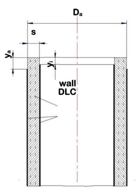
A calculation was carried out to fi nd how much such a overcoating would influence the heat transfer in first place, as the DLC-layer works as barrier for heat transfer. Fig. 3 shows a model for the coating of such a tube in a reactor. The results of tests were that the decrease in coating thickness inside starts with the value h0, and after a certain length l0 it decreases with an exponential function down to h½ at position ½ in the middle. Outside the thickness h0 though remains constant, however. Assuming the values listed below, two cases were calculated, as there is wide range given for the heat transfer rate of DLC (a-C:H – type) in [Bob18]. In the case of λDLC,1 = 1 W/Km the additional average heat resistance was R₁ = 0,35·10-⁴ [m² ·K·W-¹], in the other case λDLC,2 = 0,2 W/Km it came to R₂ = 1,75·10-4 [m² ·K·W-¹], so the average heat resistance is Ravr = 1,05·10-⁴ [m² ·K·W-¹].
Values:
h₀ = 20,3 µm (calculated layer thickness at the ends)
h½ = 8 µm (given layer thickness inside, middle position) l = 180 mm (calculated length of constant thickness)
l = 1600 mm (length of thought tube)
s = 2 mm (wall thickness) material: 1.4571 (stainless steel)
λSt = 15 W/Km (heat transfer rate stainless steel)
λDLC = 0,2 to 1 W/Km (heat transfer rate DLC acc. [Bob18])
In order to bring this effect into the perspective of data published in [Ged07] for a CaSO4-H2O solution (2,5 g/l) on stainless steel, wall temperature 75 °C and fluid temperature 42 °C, which is referred to as “experimental data” in Fig. 4. A loss on heat transfer capacity with a DLC coating is present from the beginning.
If the combination of type of DLC, fluid and wall temperature is set well, the induction period (tind) is substantially longer, and the formation can be expected to be less intense. In the same way the tube is easier to clean, which leads to shorter down times. Fig. 4 shows that the total heat transfer over time is much higher than without DLC coating, because the losses correspond with the area below the fouling curve in the diagram.
In the experimental data the induction period was determined to be 85 hours, while after 130 hours there is a break even after that the DLC-coated layer gains its substantial benefit. Some measures can be taken to lower the initial resistance of the DLC-type system. Firstly, the tube can be coated on one side only, so in cases where a side is known to be permanently clean, the coating can be omitted. The other option is to reduce the layer in the middle to a lower thickness when abrasion is less of an issue. If shorter tubes are used, the initial thickness h0 is smaller, but this is for more orbital welds that are necessary.
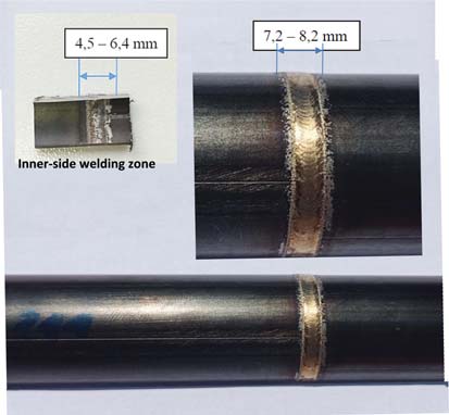
The orbital welding tests at Polysoude (Fig. 5) indicated that the weld joints should not be coated. Although orbital welding was possible even with fully coated ends (Fig. 6), there was a small increase in carbon content found in the weld seam using the GDEOS method, but this is likely to be disadvantageous in demanding applications. The micrograph also showed some less favorable grain formations. Further tests will be performed acc. Fig 7, which would be possible at the industrial scale without much effort; for instance, a simple cape can be used during the coating process to prevent the layer from be applied to the surface in weld zone. The tests revealed that uncoated lengths between 6 and 8 mm were measured after pickling (Fig. 6), ya = 4 mm and yi = 3mm is an option (Fig. 7).
Conclusion and outlook
Subsequent steps in gaining additional knowledge of DLC-type coatings in shell and tube heat exchangers will first comprise test tubes acc. C-route (cavity coating) and later those made acc. G-route (gap coating). Only long-term tests under real conditions will bring the required feedback about benefit and durability in heavy duty applications with great pressure and high temperature up to 450°C.
For the researchers of University of Applied Sciences Upper Austria, Wels, Austria, the realization of and feedback from such tests will show, whether DLC-type coatings will enhance fouling and cleaning to a major extent with a wide range of applications.
Acknowledgement
Proofreading by D. L. Vaught is gratefully acknowledged.
About the author
Dr. Albert Angerbauer University of Applied Sciences Upper Austria School of Engineering/Environmental Sciences Stelzhamerstraße 23 4600 Wels +43 (0)50804-44070 albert.angerbauer@fh-wels.at
References
[Ang21] Angerbauer, A., Gangl, R., Malfent, M., Forsich, C., Heim, D., „Prevention of fouling using DLC in shell and tube heat exchangers”, Nov. 2021, Heat Exchanger World, KCI-Publishing
[Ang22] Angerbauer, A., Gangl, R., Malfent, M., Forsich, C., Heim, D., “Prevention of fouling using DLC-coating in shell and tube heat-exchangers”, European Heat Exchanger, World Conference & Expo, 1 & 2 November 2022 – Rotterdam, Netherlands
[Aug09] W. Augustin, I. Bialuch, “Schlussbericht IGF-06/01 – Verbesserung des Fouling- und Reinigungsverhaltens wärmeübertragender Flächen durch optimierte Oberflächenbeschichtung (Fortsetzungsantrag)” [Online]. Available: https://www.efds.org/wp-content/uploads/2016/05/IGF-06-01-Schlussbericht.pdf [Accessed 05-09-2021]
[Bob18] K. Bobzin, T. Brögelmann, C. Kalscheuer, M. Thiex, M. Ebner, T. Lohner, K. Stahl, “A contribution to the thermal effects of DLC coatings on fluid friction in EHL contacts,” Lubrication Science 30, Whiley, 2018
[Ged07] T. Geddert, I. Bialuch, W. Augustin and S.Scholl, “Extending the induction period of crystallization fouling through surface coating,” 7th International Conference on Heat Exchanger Fouling and Cleaning – Challenges and Opportunities, Tomar, Portugal, July 1 – 6, 2007
[Pil21] Pillaca E.J., Trava-Airoldi V.J., Ramírez M.A., “Axial distribution improvements of DLC film on the inner surface of a long stainless steel tube”, Surface & Coatings Technology 412, 2021
[Pol16] Polysoude SAS, “The orbital welding handbook”, Polysoude SAS, Nantes, France, 2016
[Ric17] K. Richter, R. Müller, D. Landgrebe, K. Siedbeneck, W. Augustin and S.Scholl, “Innenbeschichtete Rohre: Ein erfolgversprechender Lösungsansatz zur Verminderung von Foulingeffekten,” 10th Expert conference on roll forming (Fachtagung Walzprofilieren), Darmstadt, Germany, February 20th, 2017
[RUB21] RUBIG Group, “Top of Nitriding and Coating – Nitriding and Coating Furnaces,” [Online]. Available: https://www.rubig.com/fileadmin/user_ upload/AT/Downloads/AT_Folder_A4_EN_20210504_digital.pdf [Accessed 08-09-2021]