^ Figure 3: Optical Micrograph of the cross-section of the cracks.

Article by Dr. Elaya Perumal Kailasanathan, Corrosion and Metallurgical Consultant, Coimbatore, Tamil Nadu, India

Site information

Four digester preheaters were replaced at about the same time. When one preheater started leaking it was taken out of service for detailed analysis. A hydro test showed that the tubes in the second pass of the exchanger were leaking somewhere in the middle. The tubes could not be pulled out easily from tube bundle: they had to be hammered out. The visual examination of these tubes gave the following information:
  • Circumferential cracks were found in the middle part, between two baffle positions
  • A series of rust spots or scratch lines was present on the outside surface of some tubes
  • Some tubes had bends
  • No apparent corrosion/rust/pitting on the inside surface
The tubes were seamless, with a size of 32mm OD x 1.5mm WT and five metres long, made of Type 316L stainless steel and manufactured in accordance with ASTM A-213. They were exposed to the following service conditions:
• Tube side:
• White liquor:
NaOH ≈76 gpl
Na2S ≈12 gpl
Na2C03≈18 gpl
• Outlet temperature:170°C
• Shell side:
Steam at 7kg/cmpressure
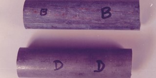
Figure 2. Tube B: sample from the replacement tubes,  having scratches and rust spots on the OD surface. Tube D:unused sample from the replacement tubes.

The original preheaters that were installed first started leaking after six years of service. The tubes were suspected to be leaking near the tube-to-tube sheet weld joints. They were plugged and operation continued. Gradually more tubes started leaking and retubing became necessary. The fabrication drawing of the original preheaters showed the following main points: the tubes were of Type 316 stainless steel; the number of baffles was 2; the working temperatures were 200°C (steam) and 170°C (white liquor). The tubes pulled out from the original preheaters showed circumferential cracks in the middle part of the tubes, between baffle positions, without pitting or wall thinning.

Sample testing

Four tube samples were obtained for testing and analysis (see figures 1 and 2). The following observations were made:
•  The original tubes as well as the replacement tubes showed similar cracking.
•  The rust spots on the replacement tubes could only be found along the scratches.
•  The unused sample showed the normal ‘white-pickled’ finish of a stainless steel tube.

Optical Micrograph

The samples were then chemically analyzed (see table 1).
The results indicated that the original lot (sample A) was of Type 316 stainless steel while the replacement lot (samples B, C and D) were of Type 316L stainless steel. Longitudinal microscopic examination showed the following common feature in both the original and the replacement tubes: Cracks had initiated from the ID-side of the tube, were transgranular and typical for stress corrosion cracking. In addition to the main crack, which caused the leakage, many small cracks were noticed on either side of the main crack (see Figure 3).
For the rest the samples showed a normal annealed structure with uniform equiaxed austenitic grains with steps.

Conclusions

Both the original and the replacement tubes were solution annealed, seamless, austenitic stainless steel tubes. The only difference was that the original tubes were made of Type 316 stainless steel while the replacement tubes were made of Type 316L stainless steel. The cracks were typical of transgranular stress corrosion cracking of stainless steels, occurring on stressed components exposed to high temperature caustics. The rust, as seen on tube sample B (replacement tubes), occurred on the scratches formed on the OD surface of the tube. These scratches were formed when the tubes were hammered out of the tube bundle.

Humidity laden with corrosive industrial gases accumulated on these scratches and led to rust formation.

Table 1. Chemical analysis of the samples.

Sample   % Carbon  % Molybdenum
 A  0.068  2.18
 B  0.023  2.19
 C  0.027  2.13
 D  0.029  2.14


Cracking

Stress corrosion cracking can occur in all standard austenitic stainless steel grades, including 316 and 316L. It instantly occurs at stresses well below the yield stress, without showing any corrosion, wall thinning, rusting or pitting. SCC requires the presence of the following factors:
• Stress.
•  Certain corrosion agents, like chlorides or caustics.
•  Temperature above the given maximum.
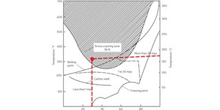
Service Limit Curves for Caustic cracking
Figure 4: Service Limit Curves for Caustic cracking showing the present condition within the SCC Region for Stainless Steel.

In this case, the corrosion agent was the alkali present in the white liquor. Figure 4 shows a summary of industrial and laboratory data on the caustic stress corrosion cracking of carbon steels and stainless steels. It is clear that with stainless steels cracking occurs at low to high concentrations of caustics at temperatures above 95°C. This environment existed on the tube-side of the preheater.

With regard to stress, in our case tube vibration may have been the cause. During a study of the drawing of the preheater, it became clear that there were only two baffles on the shell side and that is not enough to support 5 metre long tubes with a thickness of 1.5mm. The lack of a sufficient number of baffles started the tubes to vibrate. In the case of vibration, maximum stress occurs at the points of maximum amplitude of vibration which are usually midway from the points of support. Therefore, in this case the main cracks occurred between the baffles.
The time to failure caused by stress corrosion cracking is an inverse function of the applied stress normalized with respect to yield strength. Typical values of yield strength of annealed seamless tubes of comparable size, made of 316 and 316L stainless steels, can be found in table 2. The yield strength of 316 is higher than that of 316L, and 316 stainless steel tubes therefore took longer to fail than the 316L stainless steel tubes did. The ductility is higher for 316L than for 316, so the strain and amplitude during vibration is higher for 316L than it is for 316, resulting in larger bowing for 316L than for 316. This is the reason why it was so difficult to pull out the replacement tubes, made of 316L stainless steel, from the tube bundle.

Table 2. Yield strength and elongation comparison of 316 and 316L.

 Material  Yield strength (kg/mm2) % Elongation 
 316  36.77  46
 316L  29.53  54


Remedial measures

Stress corrosion cracking can be prevented by altering the operation parameters, if possible, or by proppi fabrication which reduces the stress, or by choosing a suitable material which should be resistant to SCC by virtue of its chemical composition, microstructure and composition.
The following materials may be considered:
•  Standard austenitic stainless steel Type 316 with the highest possible yield strength and wall thickness.
•  Ferritic-austenitic duplex stainless steels like AF 2304 and AF 2205, which are basically resistant to stress corrosion cracking.
In this case, as with many other cases, a change in operating parameters is not possible. Proper fabrication includes better rigidity by an increased number of baffles which will reduce vibrational stresses.
One moral out of this case study: 316L SS is more expensive than 316 SS. This does not mean that 316L SS is better than 316 SS for all corrosive applications.

About the author

Elaya Perumal Kailasanathan
Dr. Elaya Perumal Kailasanathan
Dr. Elaya Perumal Kailasanathan is a Metallurgist from the Indian Institute of Science, Bangalore, India (IISc) and Massachusetts Institute of Technology, Cambridge, Massachusetts, USA (MIT), with a specialization in the Corrosion of Chemical Process Equipment. After working for two decades at the Indian Department of Atomic Energy as a Theoretical and Applied Scientist, Engineer, and Guide, he currently works as a freelance consultant extending advisory consultancy services to the process industries, particularly, the chemical process industry in the fields of Corrosion and Metallurgy. He is the primary author of the book ‘Corrosion Failures’, published by John Wiley USA. He is also the recipient of a Lifetime Achievement Award by the NACE India Chapter. Dr. Perumal can be reached at keperumal@gmail.com

Previous articleSACOME redesigns I-TFM-I heat exchangers in a WWTP
Next articleFeatured Story – The multisectoral skills of a heat transfer engineer
Heat Exchanger World Publisher
Heat Exchanger World is a leading international magazine covering all aspects of the product supply chain of heat exchangers. Heat Exchanger World is part of the KCI Group of Companies. We are a leading knowledge, communication and information company connecting business-to-business professionals by building and sustaining global communities, solving their information needs and helping them to develop their professional life and friendships.