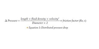
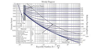
The fouling deposit reduces the inner diameter of the pipes, thereby reducing the dimension of the fluid passage and eventually increasing the fluid speed. A further contribution to higher pressure drops comes from the increase in surface roughness caused by the fouling deposit. The friction factor, at high Reynolds numbers, as it can be seen in Fig 1, is only dependent on the relative roughness of the pipes. Therefore, the graph shows how easily an increase in surface roughness can result in a significant increase in pressure drops. The fact that fouling enhances localized corrosion due to differential aeration, cavitation, and erosion should also not be neglected.
Most of the fluid passing through a HE will cause fouling. The extent of fouling depends on various factors, such as the fluid speed, composition, and temperature. Some factors cannot be changed since they result from the existing plant layout and the production process.
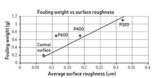
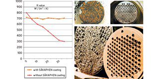
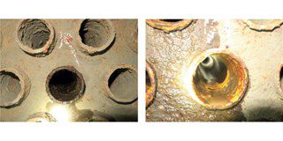
A commonly evaluated design choice is the application of a SÄKAPHEN® coating tube side and/or shell side, depending on the process. At a first glance, the application of an additional polymeric layer over the exchange surface suggests a decrease in performance due to the additional thermal resistance. In reality, the additional resistance is small as the SÄKAPHEN® coating has a thickness of only 200 [μm] and it is compensated by the reduction in fouling, which is usually thicker and less conductive than the coating. The accumulation of fouling is reduced thanks to the lower surface roughness of the coating compared to uncoated CS as shown in Fig. 2 [1].
Quantifying the above observations, a HE unit is examined that is coated by the Donelli Group, Italy in its ISO 9001 and 14001 qualified workshops in Voghera, Italy, for a mayor client in the oil & gas industry.
The unit is a 1:1 water-water HE with a volumetric flux of 100 [l/s] on both sides. The fluid speed is 2 [m/s] on both sides. On the hot side the inlet temperature is 100 [°C] and has an outlet temperature of 50 [°C]. The inlet temperature on the cold side is 20 [°C]. The tubes are carbon steel ¾ inch gage 14. The ‘average water’ fouling factor defined by TEMA (0.35 [K*m^2/kW]) is assumed on the tube side. Carbon steel conductivity is assumed with 30 [W/m/K].
Two coatings, with a dry film thickness of 200 [μm], are considered:
• SÄKAPHEN® Si 57® E 2.54 [W/m/K] (SI57E):
• SÄKAPHEN® Si 570 AR 4.79 [W/m/K] (SI570AR
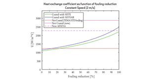
The graph hereafter shows how a fouling reduction of about 15% is sufficient to compensate the extra resistance caused by the coating. Any further reduction will result in a noticeable improvement in heat exchange coefficient.
Interestingly, the exchange coefficient λ of a newly built HE made of carbon steel protected with SÄKAPHEN® baked linings is comparable to the exchange coefficient λ offered by a newly built stainless steel HE.
Other than the stainless steel HE, the SÄKAPHEN® coated HE made of carbon steel has a significantly lower CO2 foot print:
Based on a cooling surface of 521m² and a weight for 1.4301 grade stainless steel of 15,86 [kg/m²/2mm] vs 15,70 [kg/m²/2mm] for S235JR+AR grade carbon steel, the bundle has a weight of 8.236kg made of stainless steel and 8.180kg if made of carbon steel.
Looking at the carbon dioxide equivalent per kilogram of bare metal and considering 7 [kg of CO
2 Eq/kg] for stainless steel compared to 2 kg of CO
2 Eq/kg for carbon steel the overall carbon dioxide for the bundle results in
• Stainless steel HE: 57.841 [kg of CO2 Eq]
• Carbon steel HE: 16.359 [kg of CO2 Eq]
Adding the CO
2 Eq for the applied coating with 4,3 kg of CO
2 Eq per kilogram of material and approx. 1,5 kg of material per m² plus the CO
2 Eq for the baking process of the coating with 2,8 kg of CO
2 Eq per cubic meter of natural gas and an average consumption 30m³ of NG for the complete baking process, the total balance looks as follows:
• Stainless steel HE: 57.841 [kg of CO2 Eq]
• Carbon steel HE with SÄKAPHEN®: 20.476 [kg of CO2 Eq]
The above values and calculations result in a reduced carbon dioxide equivalent of 65% up front! Looking at the reduced energy costs due to the reduced pressure drop resulting from a smoother surface of a SÄKAPHEN
® coated HE compared to corroded/fouled surfaces and even new steel surfaces derived from the table in Figure 1, the following surface roughness is assumed:
• The new HE has roughness comparable to structural steel: 0.025 [mm]
• The coated HE has roughness comparable to plastic: 0.0025 [mm]**
• The corroded/fouled HE has roughness comparable to cast iron: 0.15 [mm]
*applies to both stainless steel and carbon steel
** surface profile of Si 57® E : 0,00111 [mm], Si 570 AR : 0,00194 [mm]
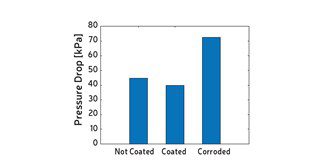
The different pressure drops derive only from the different roughness. As it can be seen in Fig. 4, the fouled/ corroded heat exchanger will have a significant increase in pressure drop compared to the brand new unit. The difference between the coated and the brand new HE is only about 10% but the brand new uncoated HE will likely develop corrosion and fouling in a short period of time while the coated HE will be significantly less affected.