^ Fouling substances on the tube surfaces of the heat exchanger

Article By Giuseppe Tommasone
___

The fouling factor represents the theoretical resistance to the heat flow due to the build-up of a layer of dirt or other fouling substances on the tube surfaces of the heat exchanger. These dirt levels are often played down by the end user in an attempt to minimize the frequency of cleaning. In reality, however, lead to an increased cleaning frequency of the tubes, if the latter have been chosen badly. Fouling mechanisms vary with the application but can be broadly classified into four common and readily identifiable types.

Common types of fouling

Chemical fouling

Chemical fouling takes place when chemical changes within the fluid cause a layer of fouling to be deposited on to the tube surface. A common example of this phenomenon is the sealing caused in a kettle or boiler as a result of ‘hardness’ salts depositing on to the heating elements as the solubility of the salts reduce with increasing temperature. This sort of phenomenon is outside the control of the heat exchanger designer but can be minimized by careful control of the tube wall temperature, which is in contact with the fluid. When this type of fouling occurs it must be removed by either chemical treatment or mechanical de-sealing processes (wire brushes or even drills to remove the scale, or sometimes even through high-pressure water jets).
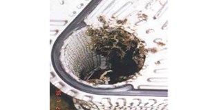
Biological fouling

Biological fouling is caused by the growth of organisms within the fluid, which deposit on to the surfaces of the heat exchanger. This type of fouling is once again outside the direct control of the heat exchanger designer but can be influenced by the choice of materials as some, notably non-ferrous brasses, are poisonous to certain organisms. When this type of fouling occurs it can normally be removed by either chemical treatment or mechanical brushing processes.

Deposition fouling

Deposition fouling occurs when particles contained within the fluid settle out on to the surface when the fluid velocity falls below a critical level. This phenomenon can be largely controlled by the heat exchanger designer as the critical velocity for any fluid particle combination can be calculated. This allows a design to be developed with minimum velocity levels that are higher than the critical level. Mounting the heat exchanger vertically can also minimize the effect as gravity tends to pull the particles out of the heat exchanger, away from the heat transfer surface even at low velocity levels. When this type of fouling occurs it is normally removed by mechanical brushing processes.

Corrosion fouling
Corrosion fouling occurs when a layer of corrosion produces build-up on the surfaces of the tube that forms an extra layer of, usually, high-thermal resistance material. This can be minimized by making a careful selection of the construction materials – there is a wide range of corrosion resistant materials available to the heat exchanger manufacturer such as stainless steels and other nickel-based alloys. One of the most misunderstood items in the heat exchanger schedule is the fouling factor, which varies per unit type.
Shell & tube heat exchanger fouling factors
Engineers are often faced with different interoffice scheduling traditions. For example, whilst we were working with a local engineer on a heat exchanger application, she asked why the office always specified a 0.0005 fouling factor on SU heat exchangers. It is important therefore tolook at what heat exchanger fouling factors are and what choices the engineer has regarding them.

What is a fouling factor in shell & tube heat exchangers?
The fouling factor is a numerical allowance for possible coating of the tubes by dirt or precipitate in the heated or cooled fluid. Fouling can occur inside or outside the tubes. It forms a very thin coating that adds resistance to the heat transfer process.
The fouling factor adds surface area to the heat exchanger but the heat exchanger can still continue to meet the required capacity even though the tubes are coated or fouled.

Why are fouling factors expressed in thousandths or tens of thousandths?
To analyze this we must look at the idea of basic heat transfer and the formula we all know well:
Q =U value x Area x LMTD
The BTUH required (Q) and the log mean temperature difference (LMTD) are fixed by the design capacities. The variables are the U value and the surface area of the heat exchanger. As the U value becomes smaller, so the surface area required to do the job increases. The U value is the inverse of the resistance in the heat exchanger to heat transfer. The U value is dependent on the fluid type, the velocity, and the materials of construction. It is not unusual for the U value of a steam-to-water shell & tube heat exchanger for hydronic heating to be in the 500-to-1000 range before adding fouling. This is a high U-value because condensing steam carries a higher temperature and a large BTU per pound. Let’s assume the number is 8oo.The inverse, resistance, would be 0.00125.If we add a fouling factor of 0.0005 to it, the result is 0.00175 and the U value becomes 571.The surface area required increases by 40%. In a water-to-water shell & tube heat exchangers, the U value is more likely to be of the order of 300 to 700.

What fouling factors should I use?
In closed hydronic heating systems, dirt and poor water quality can affect many products other than the heat exchanger. For this reason, we go to great lengths to make sure these systems are clean. Clean systems promote less fouling in shell & tube heat exchangers. The U value is also greatly affected by the fluid type and temperature. Glycols will lower the U value. Lower temperatures will lower the U value. The material of construction can also change the U value. The old rules of thumb for 0.001fouling factors is just too conservative for today’s more precise methods of determining capacities. In addition, the larger fouling factor provides a solution with a larger heat exchanger that is not ‘green’. It would be possible to use 0.0008 for water-towater heat exchangers. This is a safe overall rule-of-thumb for liquid-to-liquid shell &tube selections with water.

The U value is also greatly affected by the fluid type and temperature. Glycols will lower the U value. Lower temperatures will lower the U value. The material of construction can also change the U value.
The old rules of thumb for 0.001fouling factors is just too conservative for today’s more precise methods of determining capacities. In addition, the larger fouling factor provides a solution with a larger heat exchanger that is not ‘green’. It would be possible to use 0.0008 for water-towater heat exchangers. This is a safe overall rule-of-thumb for liquid-to-liquid shell &tube selections with water.

What fouling factors should I use for plate heat exchangers?
The fouling factor of plate heat exchangers must be 1/10 of that of shell & tube heat exchangers as API 662 recommends. There is confusion among process engineers on the fouling factors to be used in plate heat exchangers and often the data sheets of EPC contractors refer to shell & tube fouling factors as opposed to plate heat exchangers. Investigations have demonstrated that these values do not giving good results in plate heat exchangers since they often results in oversized units with premature fouling due to reduced velocity and turbulence.

The advantages of compact heat exchangers over shell & tube ones at a glance are:
  • larger heat transfer coefficients;
  • smaller heat transfer surfaces required;
  • lower fouling due to high fluid turbulences (self-cleaning effect);
  • significantly less installation and maintenance space required;
  • a lighter weight
  • a simplified cleanability especially for plate heat exchangers;
  • lower investment costs;
  • a closer temperature approach;
  • pure counter-flow operation for plate heat exchangers.
Deposits create an insulating layer over the surface of the heat exchanger that decreases the heat transfer between the fluids and increases the pressure drop. The pressure drop increases as a result of the narrowing of the flow area, which increases the gap velocity (Wang et al., 2009). Therefore, the thermal performance of the heat exchanger decreases with time, resulting in an undersized heat exchanger and causing the process efficiency to be reduced. Heat exchangers are often oversized by 70 to 8o%, of which 30 to 50% is assigned to fouling. While the addition of excess surface to the heat exchanger may extend the operation time of the unit, it can cause fouling as a result of the over-performance caused by the excess heat transfer area; because the process stream temperature changes more than desired, requiring the flow rate of the utility stream to be reduced.

As a result of the effects of fouling on the thermal and hydraulic performance of the heat exchanger, additional costs are added to the industrial processes in the form of energy losses, lost productivity, manpower, and cleaning expenses. All these can be extremely costly.
The annual cost of dealing with fouling in the USA has been estimated at over $4 billion (Wang et al., 2009).The manner in which fouling and fouling factors apply to plate exchangers is different from tubular heat exchangers. There is a high degree of turbulence in plate heat exchangers, which increases the rate of deposit removal and, in effect, makes the plate heat exchanger less prone to fouling. In addition, there is a more uniform velocity profile in a plate heat exchanger than in most shell & tube heat exchanger designs, eliminating zones of low velocity, which are particularly prone to fouling.
Fig. 2 shows the fouling resistances for cooling water inside a plate heat exchanger in comparison with fouling resistances on the tube-side inside a shell & tube heat exchanger for the same velocity. A dramatic difference in the fouling resistances can be seen. The fouling resistances inside the plate heat exchanger are much lower than that inside the shell & tube heat exchanger.

Fouling inside a heat exchanger can be reduced by:

  • using an appropriate heat-exchanger design;
  • making the correct selection of heat-exchanger type;
  • choosing the correct mitigation methods (mechanical and chemical);
  • choosing the correct heat exchanger surface modification/coating

I have my own personal experience with regards to this fouling factor discussion. Working for a large oil & gas EPC in Italy, I was told to design a heat exchanger with standard fouling factors for a monoethanolamine gas sweetening job despite my argumentation to the contrary. After installation, I received a phone call to inform me that the unit was not performing according to specifications. I suggested opening up the plate heat exchanger and taking away 50% of the plates and then restarting. After this the performance was perfect. 

Previous articleAPROVIS supplies exhaust gas heat exchangers in Europe
Next articleNew plate heat exchanger from FUNKE
Heat Exchanger World Publisher
Heat Exchanger World is a leading international magazine covering all aspects of the product supply chain of heat exchangers. Heat Exchanger World is part of the KCI Group of Companies. We are a leading knowledge, communication and information company connecting business-to-business professionals by building and sustaining global communities, solving their information needs and helping them to develop their professional life and friendships.