
Fouling mitigation using design and process-related changes
In this series of articles we will look at how heat exchangers foul, how to understand the root causes of fouling, and how to mitigate the impact of fouling. The material presented is based entirely on the author’s experience and analysis of operating situations in the Oil & Gas industry. However, many theories and varied experiences exist across the industry and amongst researchers.
By Himanshu Joshi, Heat Exchanger Specialist
In Part 4 we saw techniques which use external hardware to mitigate fouling. This month we will continue to look at fouling mitigation, but with changes to the heat exchanger geometry or to the fluid conditions like flow and temperature. Recall from Part 1 these most likely causes of fouling – single phase fluids foul due to deposition of particles, boiling services foul due to high wall temperatures leading to a wet-dry wall condition, and condensing services foul due to precipitation of salts at the tube wall and flow patterns which enable deposition or prevent the redissolution of the salts.
Shear stress (velocity) in single phase
Deposition of particles is controlled by two competing effects, fluid shear at the wall (τ) and the attraction between the solids and the tube surface. For a specific situation where the type of particles and the tube metallurgy (surface characteristics) are fixed, shear stress controls the rate of deposition. This behavior is seen both in liquids and gases. Increasing the shear stress is a very effective method to minimize fouling driven by deposition.
Although shear stress correlates with velocity (V), it is fundamentally a better parameter to use because it accounts for fluid properties, mainly the viscosity. Field and pilot-plant data has shown that the rate of fouling (increase in fouling resistance per day) varies as (τ)−ª on the tube side, and (τ)-ᵇ on the shell side, where a is in the range of 1.0-1.2 and b is about 0.6. A substantial amount of data is available for the tube side, but relatively little for the shell side, so the latter relationship has more uncertainty. Another uncertainty on the shell side is that there are many flow paths and there is no exact calculation of velocities and shear stresses. Most commonly we use the crossflow shear stress.
The exponential relationship between fouling rate and shear stress means that as shear increases the fouling rate will eventually flatten out, see Fig. 1.
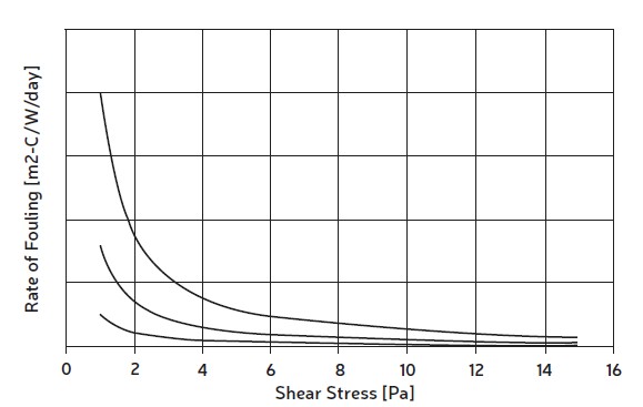
Data for the tube side shows this happens at about 10-12 Pa, beyond which little can be gained by increasing shear stress. The recommended value of tube side shear stress for minimum fouling is 10 Pa, which for most liquids will correspond to velocities between 2.0-2.5 m/s. Fig. 1 shows the fouling rates for three different fluids, varying by an order of magnitude, but they reach exponential lows at similar values of shear stress.
The best method to increase tubeside velocity is by changing the number of tube passes. Changing two passes to four doubles the velocity and reduces the fouling rate by about 60%, or four passes to six increases velocity by a factor of 1.5 and reduces fouling by about 40%. The price paid for an increase in velocity is increased pressure drop which varies as V²*L, where L is the length of the flow path. Thus, when two passes are changed to four, the velocity and flow length both double, and the new clean pressure drop is approximately eight times. That much higher pressure drop may not be available but note that fouling also increases pressure drop and it may be that a factor of eight is already encountered in actual operation for severe fouling situations.
For the shell side, from a practical standpoint it is not possible to increase velocity beyond about 0.75 m/s for liquids. This is because as the baffle spacing is narrowed to increase velocity, the flow gets diverted away from the crossflow component to the various “leakage” paths and the crossflow shear does not increase significantly. There is also a fabrication limit on baffle spacing with the minimum standard being 20% of the shell diameter. Additionally, very little field data has been analyzed for the shell side and there is no reported pilot plant data to assign shear stress recommendations. Therefore, the general recommendation is to have shell side crossflow velocities at 0.75 m/s or higher to minimize fouling.
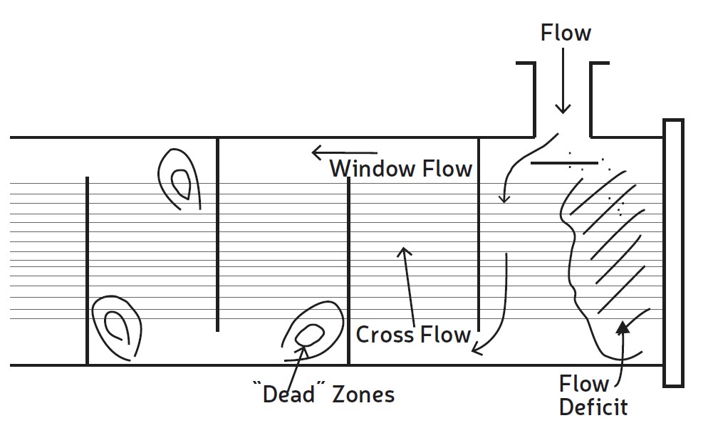
Another factor which affects shell side deposition is the presence of low velocity circulation zones (aka “dead zones”), where particles can get trapped and cannot be swept away by the force of the fluid. These zones are the physical effect of the change of flow direction around baffle edges, see Fig, 2. Deposition in these corners can be minimized by making the crossflow and window velocities approximately equal, which minimizes the size of the dead zone. Also, a large spacing in the outlet and inlet areas leads to low flow near the tubesheets and promotes deposition.
Reboilers
As explained in Part 1, a wet-dry wall and the phenomenon of film boiling lead to deposition of insoluble material such as polymers or salts, which stay on the surface and may undergo thermal conversion to coke-like material over time. One or more of the following three conditions contribute to this mechanism – the presence of insoluble material, a surface temperature high enough so that a liquid film cannot be sustained on the tube wall, and excessive vaporization or vapor flow (especially locally) such that there isn’t sufficient liquid to keep the surface wetted (vapor blanketed surfaces).
It may not be possible to avoid the presence of insoluble precursors as they are part of the process. However, some mitigation can be achieved by minimizing their formation or their quantity. An example is that of dienes which cause fouling in oil-refining reboilers. The composition of the feed to the process unit can be changed to minimize the component carrying the dienes, or the conversion of dienes to insoluble polymers can be limited by controlling reboiler temperatures.
The phenomenon of wet-dry surfaces can be controlled by limiting the heating medium temperature and by ensuring as much as possible that liquid can reach all of the boiling surface. A liquid covered surface is less likely to allow deposition to occur and therefore keep fouling from occurring. Lowering the heating medium temperature reduces the temperature driving force for heat transfer and may cause a loss in heat duty, but it may be a smaller loss than created by fouling, or it may allow a longer run length before cleaning is required.
The phenomenon of excessive vapor flow can be due to two reasons. First, the operation may be such that sufficient liquid is not fed to the reboiler, and if the heat duty is fixed it necessarily means more vapor is generated. Second, the flow patterns in the heat exchanger might be such that parts of the heat transfer surface are starved of liquid and therefore are vapor blanketed. The latter also occurs in steam generators if proper liquid circulation is not maintained.
Condensers
Overhead condensers typically foul due to precipitation of salts as the condensing fluid cools. Two design strategies can be effective against this mechanism. First, the design should allow for uniform condensation in the heat exchanger by ensuring that vapor reaches all the surface and condensed liquid can be available to sweep away some of the precipitated salts. Second, a wash stream can be injected in the incoming vapor to dissolve precipitated salts – for example, water for water soluble salts, assuming it is acceptable for the process.
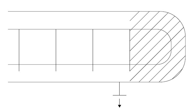
In the case of wash streams, it is necessary to ensure that the wash stream can reach all the fouling locations on the shell side, or uniformly to all tubes for tubeside condensation. Fig. 3 shows the shell side exit where the location of the nozzle is such that only very little of the vapor, condensed liquid, or the wash stream can get to the shaded area and rapid fouling occurs there. One possible solution is to place the nozzle as far to the right as possible, or to truncate the length of the tubes so that all the surface is located to the left of the nozzle.
Mitigation Economics
All techniques described above and those in Part 4, require expense in terms of capital, engineering, replacement of tube bundles, increased pressure drop, and most importantly if process changes are considered. Although a mitigation action may look expensive when only its cost is considered, it often pays off to look at the savings provided by the
mitigation and evaluating a longer-term return on the expense. In a future article we will take a detailed look at the economics of fouling and fooling mitigation.
Catch up on Fouling Focus!
Have you missed the earlier installments of this multi-part series? All articles are available in our online archive:
Part 1 – https://heat-exchanger-world.com/heat-exchanger-fouling-in-practice-understand-mitigate-1/
Part 2 – https://heat-exchanger-world.com/heat-exchanger-fouling-in-practice-understand-and-mitigate-part-2/
Part 3 – https://heat-exchanger-world.com/heat-exchanger-fouling-in-practice-understand-and-mitigate-part-3/
Part 4 – https://heat-exchanger-world.com/heat-exchanger-fouling-in-practice-understand-and-mitigate-part-4/
Upcoming in Part 6
In the next article we will look at cleaning of fouled heat exchangers. Although it is not a direct mitigation action, it is an important aspect of minimizing the cost of fouling. The article will cover different cleaning methods, their relative costs and effectiveness, and the cost of not cleaning a heat exchanger to a fully clean condition.
About the authors

Himanshu Joshi retired from Shell in 2021 after 34 combined years with ExxonMobil and Shell, during which he specialized in heat exchangers and fouling. He was part of a team that was granted a patent related to fouling deposit analysis at ExxonMobil, and led applied fouling R&D projects at both companies. He has made several presentations about the field aspects of fouling and fouling mitigation, and deployed many mitigation technologies in the field. He can be reached by email at alph.hmj@gmail.com.
About this Technical Story
This Technical Story was first published in Heat Exchanger World Magazine in February 2024. To read more Technical Stories and many other articles, subscribe to our print magazine.
Technical Stories are regularly shared with our Heat Exchanger World community. Join us and share your own Technical Story on Heat Exchanger World online and in print.