Spiral tube heat exchangers (STHE) have been used for many years. In fact, they have been used since the beginning of the cryogenic liquefaction industry in the early nineties. They were developed by Linde under the industrial name of coil-wound heat exchangers (CWHE) and were used for the first time on an industrial unit of liquified air in 1895.
By Christophe Gajecki and Ren Hongliang
Zhenhai Petrochemical Jianan Engineering Co., Ltd (ZPJE) is an independent joint-stock company established in the Ningbo region on the Chinese east coast. The company has more than 700 employees specialised in spiral tube exchangers manufacturing, thermal and hydraulic calculation, R&D, and project management. For more than 30 years, ZPJE has developed a unique knowledge of heat exchange calculation, hydraulic simulation, and mechanical modelling of spiral tubes design to enable this technology to be used in refinery, petrochemical, and oil & gas applications. The idea was to use the advantage of the spiral tube technology, enabling very large surfaces packed in a single exchanger, and to apply it to hydrocarbon fluids at high pressures and temperatures.
ZPJE was able to develop its technology based on an extensive expertise of the various processes and was driven by the feedback and needs of its customers. It can accommodate the various demanding process conditions combining very high thermal and hydraulic performances, with the robustness needed in such demanding industries.
Since 1999, ZPJE has delivered more than 1450 exchangers, with units operating for more than 24 years. The complete installed base accumulates 5600 years of efficient and reliable operation. After 25 years of experience in China, and with the support of main international licensors, they are now ready to provide their experience to the worldwide market with already 24 references sold outside China.
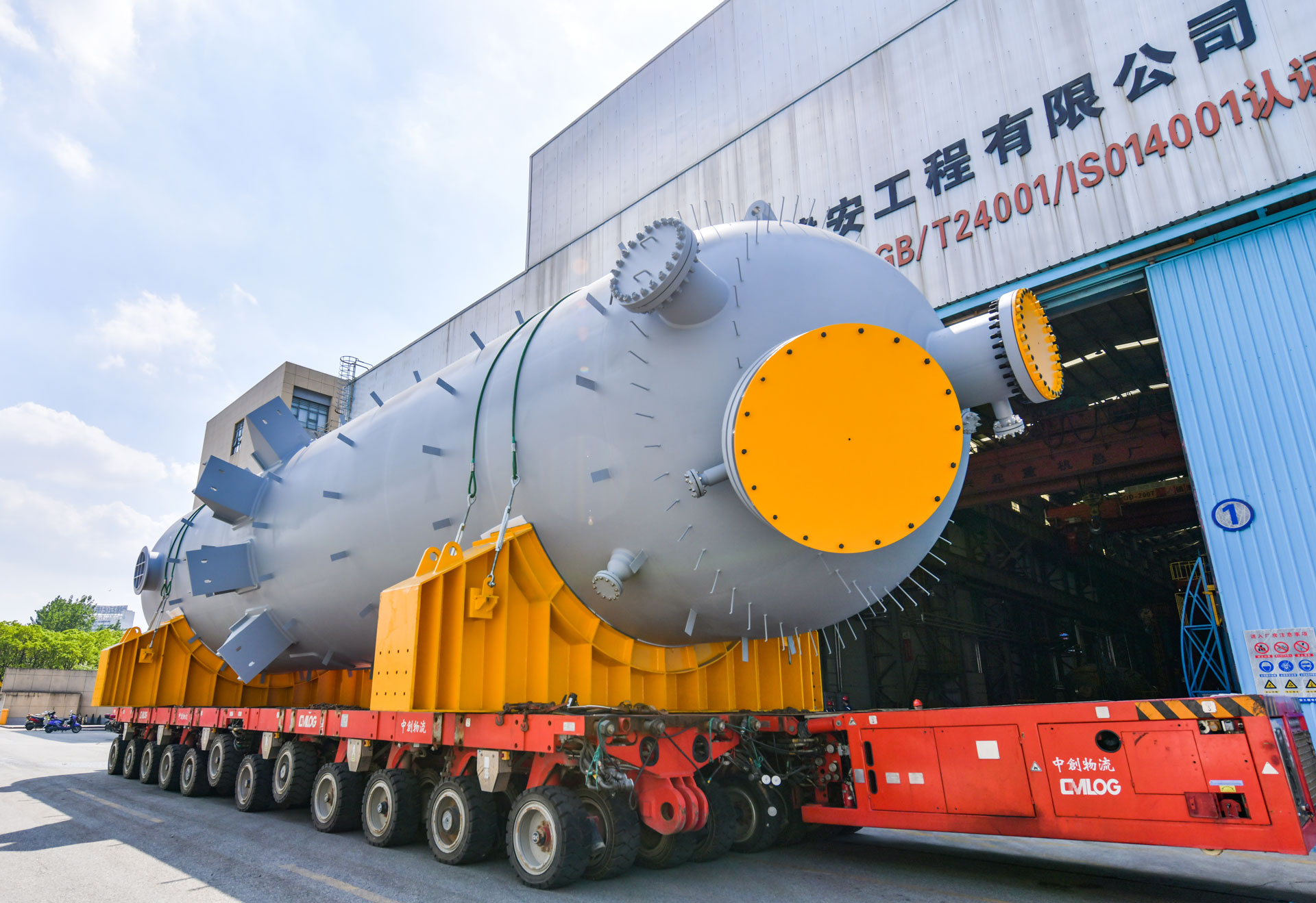
ZPJE comply with several certifications:
■ PED 4.3 (for tubes) qualified by E.U.
■ A1, A2 pressure vessel design and manufacturing licenses in China
■ ASME authorisation certificates of U & U2.
■ ISO 9001:2015
■ ISO 14001:2015
■ ISO 45001:2018
Design
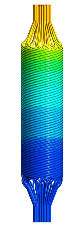
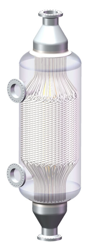
The design of spiral tube heat exchangers consists of two main components: the tube bundle and the pressure vessel. The inside bundle is formed by many seamless tubes arranged in multiple layers of helical coils, around a centre pipe. This tube bundle is then horizontally inserted inside a fully welded cylindrical pressure vessel to complete the fabrication of the heat exchanger. The fluid on the tube side and on the shell side flows in opposite directions, making the equipment a true countercurrent heat exchanger.
The flexible spiral wound tube bundle is acting as a spring, expanding or shrinking during the start-up or shut down phases. This allows for a differential expansion between the bundle and the pressure vessel required to ensure its mechanical integrity. This expansion is guided axially by the centre pipe. In fact, there are no mechanical limitations in temperature rise and fall, making this technology highly reliable under process fluctuations. It allows for very low constraints on start-up/shutdown procedures and emergency situations.
This patented design gives:
• Resilience under upset conditions.
• Resistance to thermal and pressure shock.
• No limit for cooling and heating rates during start-up, shutdown and upset conditions within the design pres-sures and temperatures.
Just one exchanger can replace multiple horizontal or vertical exchangers, saving on installation and capital cost for both new units or revamping projects. Compared to a traditional shell & tube exchanger, the spiral tube exchanger has a smaller volume and weight due to its high heat transfer efficiency. It can offer a heat exchange up to 30,000 m² for reforming and aromatic processes, and up to 10,000 m² for hydroprocessing units in a single piece.
On the tube side
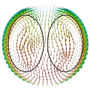
The Helix-pattern flow in the tubes creates, thanks to the centrifugal forces, a secondary flow consisting of a pair of vortices enhancing the heat transfer coefficient at the peripheral of the tubes. In order to limit the mechanical constraints, the spiral tubes are coiled layer by layer in opposite directions to ensure a homogeneous heat transfer and temperature gradient all along the exchanger, from the cold to section with higher temperatures.
On the shell side
The high turbulence flow on the shell side is created by the design of the tube coils. The variation of the fluid velocity between the tubes and the layers creates a pulse-surge collision flow regime, subsequently increasing the heat exchange coefficient outside the tubes.
The possibility of fouling is greatly limited by the non-baffle design and the absence of a stagnant zone, the turbulence of the fluid and the very low surface roughness of the tubes.
Performances
With the spiral tube design, the heat transfer efficiency is 2 to 3 times higher than conventional shell and tube heat exchangers. It allows for an achievable hot approach temperature as low as 10°C for feed/effluent exchanger on the reactor loop of the hydroprocessing units, for example. With this very high heat recovery, the charge heater can even be used only during the start-up and then shut-down during the normal operation; the temperature of the pro-cess being controlled by a by-pass line.
The minimum temperature difference between the two fluids (pinch point) can be as low as 2°C. The minimum pressure drop on shell side is 2 to 3 kPa, and the operating ranges up to 650°C for the temperatures and 26 MPa for the pressures. There is no limitation on reverse pressure between the shell and the tube sides.

Fabrication
ZPJE is using a class 100,000 dust-free clean workshop to fabricate its exchangers. It provides an exceptional manufacturing environment usually only used in semi-conductor or photovoltaic industries. In order to fabricate its very large bundle, the company developed a homemade automatic tube winding system using a tube straightener, a constant-pressure tube output controller, an angle regulator to ensure a constant pitch and precise angle between the different layers and an automated guided vehicle.
This unique manufacturing equipment guarantees a reliable and very precise fabrication, with extremely low fabrication tolerances, even on a very large assembly of kilometres of tubes.
Another key parameter for the robustness of heat exchangers at high pressure and temperature is the tube to tubesheet joint procedures.
For the tubesheet, the precision deep hole drilling tech-nique is giving a tube hole roughness Ra of 1.6, and a bore diameter deviation lower than +/- 0.05 mm. For the tubes, the diameter deviation is lower than +/- 0.05 mm.
The tube to tubesheet joints can be strength welds with hydraulic expansion or inner bore welds depending on the requirements of the process. The strength welds are performed by an automatic visual tracking and positioning system robot. Whereas X-ray is used to control the quality of the joint on strength welds, anode rod X-ray and CR imaging are used for inner bore welds.
Tube material:
The tubes can be made of carbon steel, Cr-Mo, stainless steel (304, 316, 321, super SS, Duplex), titanium and high nickel alloy (Incoloy 825, Inconel 600). The maximum seamless tube length can be more than 100m, with a surface roughness <Ra 0.3.
Shell material:
The shell material can be made of carbon steel, Cr-Mo, stainless steel and titanium. For the biggest units, the diameter can go up to 6,000 mm with a weight over 700 metric tons.
About the authors
 Mr Christophe Gajecki is a sales strategy consultant. His expertise is in sales & marketing of heat transfer equipment for refinery and petrochemical industries. Since 1997, he has worked for fired heaters and heat exchangers manufacturers, selling and managing sales team on long-term complex international projects. For more information, please send an email to: christophe.gajecki@htransferconsulting.com
 Mr Ren Hongliang is the chief engineer of Design and Research Institute of ZPJE. With 30 years of experience, he specialised in mechanical design of pressure vessel and spiral tube heat exchanger for different processes. Since 1992, he has worked for STHE research, design, and is managing design and technical teams.
About this Featured Story
This Featured Story was first published in Heat Exchanger World Magazine in November 2022. To read more Featured Stories and many other articles, subscribe to our print magazine.
Featured Stories are regularly shared with our Heat Exchanger World community. Join us and share your own Featured Story on Heat Exchanger World online and in print.


