This article aims to define the major TEMA constructions and identifies the advantages, limitations, and applications suitable for each type.
By Mihir M. Patel – Author of Mihir’s Handbook of Chemical Process Engineering
The shell and tube heat exchanger design is the most common in industry. Usually, exchangers are specifically designed and fabricated for each service; very little heat exchange equipment can be purchased off the shelf.
It is recommended that heat exchangers are designed through computer programming tools such as HTFS (now Aspen EDR) or HTRI. Certain specifications, such as exchanger type, tube length and size, and material preference are usually supplied by the end user. If the end user has no specific requirements, economics should dictate the unit chosen. TEMA (Tubular Exchangers Manufacturing Association) is the preferred standard for the manufacture of shell and tube heat exchangers. The general descriptions of the three major TEMA classes are:
- TEMA C – General Service
- TEMA B – Chemical Service
- TEMA R – Refinery Service
TEMA R is the most demanding standard, while TEMA C is the least. TEMA B and TEMA R are similar in scope, with TEMA R also mandating recessed flanges and tube sheets or spiral wound gaskets with ring construction. Additionally, TEMA R requires some components to have a greater minimum thickness. TEMA designations refer to the front head design, the shell design, and the rear head design. For example, a TEMA type BEM has a type B front head, a type E shell, and a type M rear head design. There are conditions such as with high vapor flows, high pressure, and temperature crossing where a combination of special TEMA feature is advantageous. For example, K type shells allow for proper vapor disengagement for reboilers, whereas J and H type shells accommodate high vapor flow.
TEMA types

TEMA standards cover the heavy-duty heat exchangers (TEMA R) as well as the lighter duty heat exchangers (TEMA C and TEMA B). Refineries typically use only the TEMA R heat exchangers due to the generally severe requirements of petroleum applications; however, more moderate process services may warrant consideration of TEMA B construction.
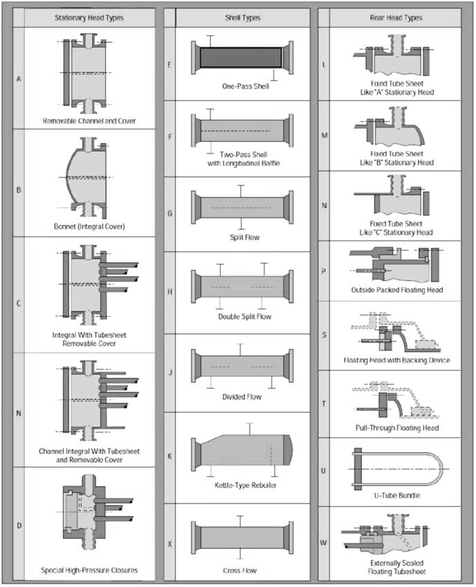
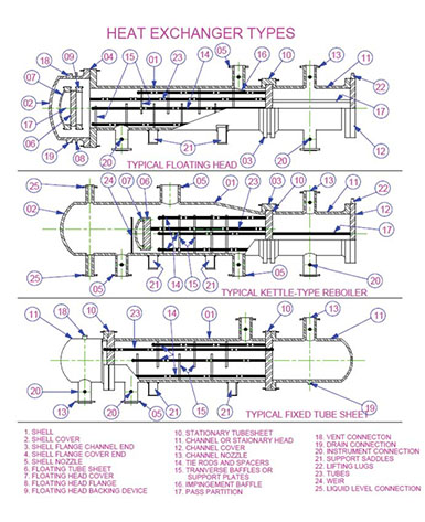
Each TEMA heat exchanger consists of the following main parts: the front-end stationary head (commonly referred to as the ‘channel’); the tube bundle; the rear head, and the shell. Each part can be designed in several modifications, commonly referred to as ‘types.’ Figure 1 depicts the five types of channels (A, B, C, N, and D), seven types of shells (E, F, G, H, J, K, and X), and eight rear end head types (L, M, N, P, S, T, U, and W) designated by the TEMA standard. The type of rear end head used determines if the tube bundle can be removed from the shell. Figure 2 provides details on parts within each exchanger type. In the following sections, you will find details of all tube types, along with advantages, disadvantages, and typical applications, as well as the distinguishing features of shell types.
Straight Tube, fixed tubesheet – Types AEL, BEM, AEM, NEN
This TEMA type is the simplest design and is constructed without packed or gasketed joints on the shell side. The tubesheet is welded to the shell and the heads are bolted to the tubesheet. On the NEN heat exchanger, the shell and the head are both welded to the tubesheet. Typically, a cover plate design is provided to facilitate tube cleaning. This TEMA category, especially the NEN, is the lowest cost TEMA design per square foot of heat transfer surface.
Advantages
• Less costly than removable bundle designs
• Provides maximum amount of surface for a given shell and tube diameter
• Provides for single and multiple tube passes to ensure proper velocity
• May be interchangeable with other manufacturers of the same TEMA type limitations
Limitations
• Shell side can be cleaned only using chemical methods
• No provision to allow for differential thermal expansion; an expansion joint on shell side must be used
Applications
• Oil coolers, liquid to liquid, vapor condensers, reboilers, gas coolers
• Generally, more viscous and warmer fluids flow through the shell
• Corrosive or high fouling fluids should flow inside the tubes
Removable bundle, externally sealed floating tubesheet – Type AEW, BEW
This design allows for the removal, inspection and cleaning of the shell circuit and shell interior. A special floating tubesheet prevents intermixing of fluids. In most cases, a straight tube design is more economical than U-tube designs
Advantages
• Floating tubesheet allows for differential thermal expansion between the shell and the tube bundle
• Shell circuit can be inspected and either steam- or mechanically cleaned
• The tube bundle can be repaired or replaced without disturbing the shell pipe
• Less costly than TEMA types BEP or BES which have an internal floating head
• Maximum surface for a given shell diameter for removable bundle design
• Tubes can be cleaned in AEW models without removing piping
Limitations
• Fluids in both the shell and tube circuits must be non-volatile and non toxic
• Tube side passes are limited to single or two-pass design
• All tubes are attached to two tubesheets. Tubes cannot expand independently, so large thermal shock applications should be avoided
• Packing materials produce limits on design pressure and temperature
Applications
• Intercoolers and aftercoolers, air inside the tubes
• Coolers with water inside the tubes
• Jacket water coolers or other high differential temperature duty
• Place hot side fluid through the shell with entry nearest the front end
Removable bundle, outside packed head – Type BEP, AEP
This design allows for the easy removal, inspection, and cleaning of the shell circuit and shell interior without removing the floating head cover. A special floating tubesheet prevents intermixing of fluids. In most cases, a straight tube removable design is more costly than U-tube designs.

Advantages
• A floating tubesheet allows for differential thermal expansion between the shell and the tube bundle
• The shell circuit can be inspected and steam-cleaned. If the tube bundle has a square tube pitch, tubes can be mechanically cleaned by passing a brush between rows of tubes
• The tube bundle can be repaired or replaced without disturbing shell piping
• On AEP design, tubes can be serviced without disturbing tube-side piping
• Less costly than TEMA type BES or BET designs
• Only shell fluids are exposed to packing. Toxic or volatile fluids can be cooled in the tube-side circuit
• Provides large bundle entrance area, reducing the need for entrance domes for proper fluid distribution
Limitations
• Shell fluids limited to non-volatile, non-toxic materials
• Packing limits the shell-side design temperature and pressure
• All tubes are attached to two tubesheets. Tubes cannot expand independently, so large thermal shock applications should be avoided
• Less surface per given shell and tube diameter than AEW or BEW
Applications
• Flammable or toxic liquids in the tube circuit
• Good for high fouling liquids in the tube circuit
Removable bundle, internal split ring floating head – Type AES, BES
Ideal for applications requiring frequent tube bundle removal for inspection and cleaning. Uses straight-tube design suitable for large differential temperatures between the shell and tube fluids. More forgiving to thermal shock than AEW or BEW designs. Suitable for cooling volatile or toxic fluids.
Advantages
• Floating head design allows for differential thermal expansion between the shell and the tube bundle
• Shell circuit can be inspected and steam-cleaned. If it has a square tube layout, tubes can be mechanically cleaned
• Higher surface per given shell and tube diameter than ‘pull-through’ designs such as AET, BET
• Provides multi-pass tube circuit arrangement
Limitations
• Shell cover, split ring, and floating head cover must be removed to remove the tube bundle; this results in higher maintenance cost than pull-through
• More costly per square foot of surface than fixed tube sheet or U-tube designs
Applications
• Chemical processing applications for toxic fluids
• Special intercoolers and aftercoolers
• General industrial applications
Removable bundle, pull-through floating head – Type AET, BET
Ideal for applications requiring frequent tube bundle removal for inspection and cleaning as the floating head is bolted directly to the floating tubesheet. This prevents having to remove the floating head in order to pull the tube bundle.
Advantages
• Floating head design allows for differential thermal expansion between the shell and the tube bundle
• Shell circuit can be inspected and steam- or mechanically cleaned
• Provides large bundle entrance area for proper fluid distribution
• Provides multi-pass tube circuit arrangement
• Suitable for toxic or volatile fluid cooling
Limitations
• For a given set of conditions, this TEMA style is the most expensive design
• Less surface per given shell and tube diameter than other removable designs
Applications
• Chemical processing applications for toxic fluids
• Hydrocarbon fluid condensers
• General industrial applications requiring frequent cleaning
Removable bundle, U-tube – Type BEU, AEU
Especially suitable for severe performance requirements with maximum thermal expansion capability. Because each tube can expand and contract independently, this design is suitable for larger thermal shock applications. While the AEM and AEW are the least expensive, U-tube bundles are still an economical TEMA design.
Advantages
• U-tube design allows for differential thermal expansion between the shell and the tube bundle as well as for individual tubes.
• The shell circuit can be inspected and steam- or mechanically cleaned
• Less costly than floating head or packed floating head designs
• Provides multi-pass tube circuit arrangement
• Capable of withstanding thermal shock applications
• Bundle can be removed from one end for cleaning or replacement
Limitations
• Because of U-bend, tubes can be cleaned only by chemical means (although nowadays, new techniques of fluid pressurized scraper, similar to a pipeline pig, are available)
• Because of U-tube nesting, individual tubes are difficult to replace
• No single tube pass or true counter current flow is possible
• Tube wall thickness at the U-bend is thinner than at straight portion of tubes
• Draining of tube circuit is difficult when mounted with the vertical position with the head side up
Applications
• Oil, chemical, and water-heating applications
• Excellent in steam to liquid applications
Shell types
TEMA E: The most common TEMA shell type is the “E” shell as it is most suitable for most industrial process cooling applications. However, for certain applications, other shells offer distinct advantages.

Chemical Process Engineering).
TEMA F: A TEMA-F shell design provides for a longitudinal flow plate to be installed inside the tube bundle assembly. This plate causes the shell fluid to travel down one half of the tube bundle, then down the other half, in effect producing a counter current flow pattern which is best for heat transfer. An F-type is suitable when pure counter flows are needed at two tube sides. This type of construction can be specified where a close approach temperature is required and when the flow rate permits the use of one half of the shell at a time. In heat recovery applications, or where the application calls for increased thermal length to achieve effective overall heat transfer, shells can be installed with the flows in series.
TEMA G and H: These shell designs are most suitable for phase change applications where the bypass around the longitudinal plate and counter-current flow is less important than even flow distribution. In this type of shell, the longitudinal plate offers better flow distribution in vapor streams and helps to flush out non-condensables. They are frequently specified for use in horizontal thermosiphon reboilers and total condensers. A G-type is used for cases with small pressure drop at the shell side. The H-type is similar to F-type but in larger units.
TEMA J: J-type shells are typically specified for phase change duties where significantly reduced shell side pressure drops are required. They are commonly used in stacked sets with the single nozzles used as the inlet and outlet. A J-type shell is usually used in cases where the maximum allowable pressure drop is greater than that with an E-Type shell. It is also utilized when tube vibration is a problem.
TEMA K: This type is used for flooded evaporation of shell side fluids. The TEMA K shell, also termed a “Kettle Reboiler,” is specified when the shell side stream will undergo vaporization. The liquid level of a K shell design should just cover the tube bundle, which fills the smaller diameter end of the shell. This liquid level is controlled by the liquid flowing over a weir at the far end of the entrance nozzle. The expanded shell area serves to facilitate vapor disengagement for boiling liquid in the bottom of the shell. U-bundles are typically used with K shell designs. K shells are expensive for high pressure vaporization due to shell diameter and the required wall thickness. A K-type is employed only for reboilers to supply a large disengagement space to minimize shell side fluid carryover.
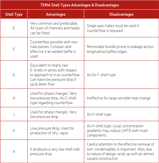
TEMA X: This shell, also known as a crossflow shell, is most commonly used in vapor condensing applications, though it can also be used effectively in low pressure gas cooling or heating. It produces a very low shell-side pressure drop, and is therefore most suitable for vacuum service condensing. In order to ensure adequate distribution of vapours, X shell designs typically feature an area free of tubes along the top of the exchanger. It is also typical to design X shell condensers with a flow area at the bottom of the tube bundle to allow free condensate flow to the exit nozzle. Careful attention to the effective removal of non-condensables is vital for X shell constructions. X-type is appropriate when the maximum shell side pressure drop is exceeded by all combinations of other shell types. Please refer to Table 1 for a summary of the TEMA shell types advantages and disadvantages.
Conclusion
This article has highlighted the TEMA types for S&T exchangers with pros & cons for major types. Having selected the TEMA type and allocation of the process fluids to shell and tube sides, the process engineer still needs to properly specify pressure drops, temperature profile and properties for the process fluids on both the shell and tube side. The engineer then needs to optimize the thermal design for the exchanger. This topic will be covered in a future article.
About the Authors

Mihir M. Patel is a chemical engineer and project management professional (PMP®) from PMI, USA, as well as a TUV SUD certified functional safety professional. He has been practicing chemical engineering for over 36 years in the chemical process Industry. Patel now shares his knowledge and experience through the format of published handbooks and training courses for chemical engineers.

