Fouling and heat exchanger design
In this series of articles we will look at how heat exchangers foul, how to understand the root causes of fouling, and how to mitigate the impact of fouling. The material presented is based entirely on the author’s experience and analysis of operating situations in the Oil & Gas industry. However, many theories and varied experiences exist across the industry and amongst researchers.
By Himanshu Joshi, Heat Exchanger Specialist
In this concluding article of the Fouling Focus series, we will look at what should be considered during the design of a heat exchanger that is expected to foul. Usually, the objective is to maintain heat exchanger performance at or above a certain heat duty until it can be cleaned, which could be as short as a few months to as long as five or six years. Two aspects are important during design – maximize the time required for cleaning which requires the designer to minimize the rate of fouling and provide a sufficient surface area margin so that a minimum heat duty can be maintained even as fouling increases over time. In part 1 we looked at how heat exchangers foul, and in parts 4-5 at how fouling can be mitigated. This article will elaborate on some of those ideas as well as provide a few more guidelines that are important during design.
Minimize fouling by design – single phase

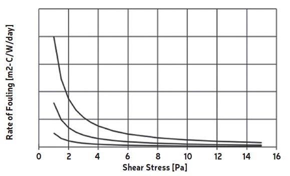
For single phase fluids the most important criterion is fluid shear stress at the wall, which is a function of velocity. High velocity has two benefits: it minimizes the rate of particle deposition, and it results in lower wall temperatures when that is a critical aspect of the fouling mechanism as in cooling water. For deposition a shear stress higher than ~10 Pa minimizes fouling with ~15 Pa as the limit beyond which little can be gained (refer to Fig. 1 extracted from Part 5). For temperature related fouling, let’s use the example of cooling water. Higher velocity, in addition to minimizing particle deposition, increases the heat transfer coefficient and lowers the wall temperature. Scaling of salts in cooling water is a function of temperature and increases greatly beyond certain limits, so keeping this temperature low reduces fouling.
An increase in pressure drop is the price that is paid for increasing velocity, so there is always a balance between whether to pay a price upfront for the pressure drop or later during operation due to fouling. A designer should strive to maintain the required velocity and ask for the required pressure drop rather than accepting a low pressure drop and producing a design more susceptible to fouling. For cases where wall temperature is critical, if you choose to use fouling factors in your design, you should simulate the heat exchanger under clean conditions (i.e., with zero fouling resistances) to get an estimate of the wall temperature at start-up. Design software may sometimes be misleading if it shows the temperature at the surface of the fouling layer, not at the tube wall.
Minimize fouling by design – boiling

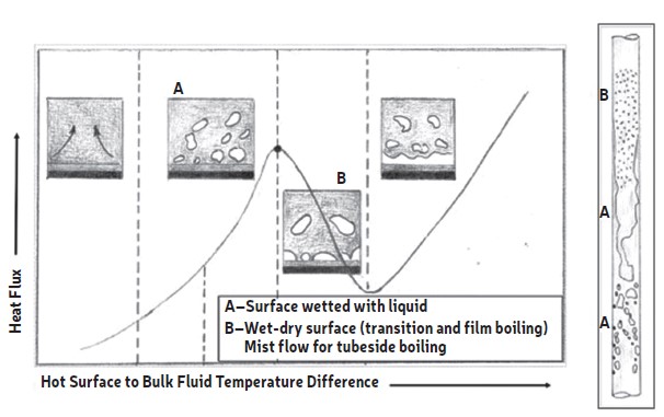
Fig. 2 (extracted from Part 1) explained the phenomenon of film boiling and how it enhances fouling. For reboilers and steam generators, the designer needs to prevent this mechanism. There are two relevant factors – a wet-dry wall due to high wall temperatures and excessive vapor generation which may result in a wet-dry wall condition even at lower temperatures. Today’s design software can estimate these flow conditions, and sometimes even which part of the heat exchanger they are most likely to occur in. The key in both cases is to keep the wall covered with liquid as much as practical. Wall temperature is usually a strong function of the heating medium temperature. Lower heating medium temperatures are less likely to produce film boiling or excessive vapor but may require higher surface area in the heat exchanger due to lower temperature differentials. There are guidelines in design handbooks about the maximum vapor fraction (usually 10-30%) in reboilers and steam generators. In the latter it is sometimes shown as a “circulation ratio” but serves the same purpose.
What the designer should be aware of is that if excessive vapor is present, it naturally creates a vapor blanket on the wall and may increase fouling. It is easier to visualize this on the tube side because the vapor fraction increases towards the outlet, but somewhat difficult on the shell side because maldistribution of the incoming liquid and outgoing vapor can create pockets of high vapor in unexpected areas. Since film boiling is temperature dependent, it is a good practice to simulate the heat exchanger design under zero fouling conditions so as to estimate the wall temperatures and the possibility of film boiling at start-up and determine possible ways to minimize fouling. Note that velocity (or shear) isn’t a major factor, it is the flow regimes, fluid composition, and wall temperature which are critical.

Minimize fouling by design – Condensers
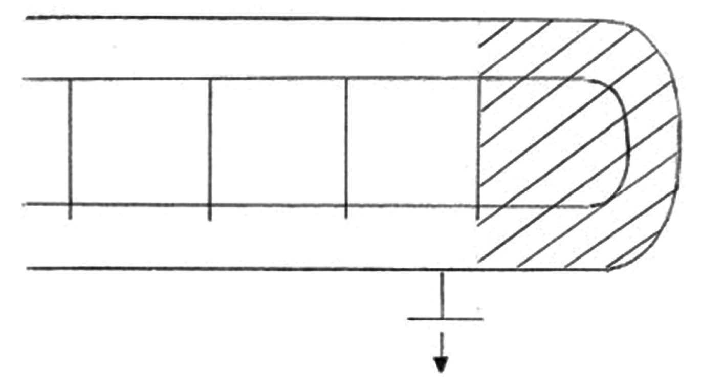
The primary mechanism for condensers fouling on the process side is that of salt precipitation, which is difficult to control with heat exchanger design. The process composition and temperatures are given and so is the need to cool to a certain temperature. The best control for heat exchanger design is to ensure that the flow reaches all the surface area (see Fig. 3, extracted from Part 5). In cases where something like a water wash is provided to dissolve precipitated salts, nozzle placement, baffle locations, and the number of inlet nozzles (for aircoolers with tubeside condensing) need to be managed to ensure an even fl ow to all shell side areas or all tubes of the heat exchanger.
Fouling Margins
The presence of precursors, mandated process temperatures and flow rates, and constraints on pressure drop will cause heat exchangers to foul even when design strategies such as those mentioned above are followed. In such cases the designer needs to provide a margin, in the form of excess surface area, so the heat exchanger can deliver the required heat duty even with fouling present. However, a time will be reached when all the excess surface is used up and the heat duty can no longer be achieved. Thus, built into how we provide margin is the notion of an operating cycle or how long will the heat exchanger perform as desired before we need to clean it to restore the performance. Providing excess surface (making heat exchangers bigger) naturally means a higher purchase cost and a higher installation cost (more weight). A bigger heat exchanger will have a larger flow area and consequently lower velocities which can lead to higher fouling. Lower velocities can also lead to unfavourable flow distributions on the shell side increasing the possibilities of dead zones. If the heat exchanger needs temperature or heat duty control, having too much surface can make control difficult. For all these reasons, fouling margin should be chosen such that it accounts for the above potential issues but at the same time provides the required performance over a desired period of time (the run-length). Alternatively, it should be recognized that the heat exchanger will need to be taken out of service for cleaning periodically.
The common way to provide margin is by adding a fouling resistance (aka Fouling Factor) on each side. This decreases the overall heat transfer coefficient, so the design requires more surface area. The values of these resistances are taken from standards, internal or external to the end user. There are several disadvantages to using standard fouling resistances, the one with the most impact being the unnecessary oversizing of heat exchangers resulting in higher fabrication costs and heavier, harder to maintain heat exchangers. In practice there are diminishing returns in providing excess surface. For example, a 100% margin (double the required surface) vs a 50% margin will not provide double the run-length.
The Standard values do not account for the different mechanisms and actions to mitigate fouling. For example, for a given single-phase fluid one would use the same value regardless of the actual operating velocities and shear stress. Nor do the standard values account for time, that is, there is no understanding of whether the heat exchanger can operate for a few months or a couple of years before cleaning is needed. Ideally, one would like to know the expected rate of fouling and the duration of operation before a cleaning is acceptable. Based on that rate (fouling/day) and the number of days, the fouling resistance at the end of the operation can be calculated and used as the design value. This information will almost never be available to the designer which results in the use of the arbitrary values from standards.
Large oversizing can be avoided by limiting the excess surface provided during design, no matter how severe the fouling is expected to be. In the author’s experience a maximum of 50% for high fouling and much less for low fouling is adequate margin for design, if all practically possible precautions are taken to minimize fouling. Beyond this no more benefit can be gained by adding surface. Note also that for some fluids which are never expected to foul, using even what appears to be a small fouling factor can result in a large increase in size. Always check the impact on size when using fouling factors for “clean” fluids.
Summary
Following the design guidelines described here can reduce the fouling during operation, but some amount of fouling is unavoidable given the nature of the fluids, operating conditions, and operating and design constraints. Fouling margin, in terms of excess surface area, is necessary to ensure acceptable operation over some desired run-length. Margin is usually provided with the use of standard fouling factors, but a designer should make the effort to not provide an unnecessarily high margin which can result from the fouling factors. Excessively large heat exchangers cost more to purchase, install, and maintain; and may not provide any improvement in the run-length before cleaning is required.
Fouling Focus series summary
This is the last in the series of articles called Fouling Focus. In all we looked at how heat exchangers foul, the cost of fouling and cleaning, how to mitigate fouling, and a few guidelines to follow during heat exchanger design. If you’re interested in reading the previous parts of the Fouling Focus series, please contact the Heat Exchanger World editor Iryna Mukha at i.mukha@kci-world.com.
Fouling and fouling mitigation workshop description
This workshop is intended for engineers who deal with heat exchangers in any capacity. For operations it provides an understanding of how and why heat exchangers foul and what action can be taken to minimize its economic impact, including monitoring. For those involved in design it will enhance your knowledge of how to minimize the impact of fouling during the design phase, including how to provide margins. For maintenance and inspection engineers you will understand what’s in the deposit, how best to clean, and what the consequences of fouling will be on the life of the heat exchanger. Fouling mitigation – how to minimize fouling – will also be presented, with details on proven techniques, their costs, advantages and drawbacks, and how to determine the most cost-effective technique for any fouling problem.
About the instructor
The workshop will be taught by Himanshu Joshi, who worked for 34 years as a heat exchanger and fouling specialist with two major oil companies. He served as the SME for fouling and heat transfer enhancement with both employers and was part of a team that was granted a patent related to fouling deposit analysis at ExxonMobil and led applied fouling R&D projects at both companies. He has made several presentations about the field aspects of fouling and fouling mitigation and deployed many mitigation technologies in the field. He can be reached by email at alph.hmj@gmail.com.
Catch up on Fouling Focus!
Have you missed the earlier installments of this multi-part series? All articles are available in our online archive:
Part 1 – https://heat-exchanger-world.com/heat-exchanger-fouling-in-practice-understand-mitigate-1/
Part 2 – https://heat-exchanger-world.com/heat-exchanger-fouling-in-practice-understand-and-mitigate-part-2/
Part 3 – https://heat-exchanger-world.com/heat-exchanger-fouling-in-practice-understand-and-mitigate-part-3/
Part 4 – https://heat-exchanger-world.com/heat-exchanger-fouling-in-practice-understand-and-mitigate-part-4/
Part 5 – https://heat-exchanger-world.com/heat-exchanger-fouling-in-practice-understand-mitigate-part-5/
Part 6 – https://heat-exchanger-world.com/heat-exchanger-fouling-in-practice-understand-mitigate-part-6/
Part 7 – https://heat-exchanger-world.com/heat-exchanger-fouling-in-practice-understand-mitigate-part-7/
Part 8 – https://heat-exchanger-world.com/heat-exchanger-fouling-in-practice-understand-mitigate-part-8/
About the authors

Himanshu Joshi retired from Shell in 2021 after 34 combined years with ExxonMobil and Shell, during which he specialized in heat exchangers and fouling. He was part of a team that was granted a patent related to fouling deposit analysis at ExxonMobil, and led applied fouling R&D projects at both companies. He has made several presentations about the field aspects of fouling and fouling mitigation, and deployed many mitigation technologies in the field. He can be reached by email at alph.hmj@gmail.com.
About this Technical Story
This Technical Story was first published in Heat Exchanger World Magazine in July 2024. To read more Technical Stories and many other articles, subscribe to our print magazine.
Technical Stories are regularly shared with our Heat Exchanger World community. Join us and share your own Technical Story on Heat Exchanger World online and in print.

