The tube-to-tubesheet joints in a shell and tube heat exchanger are critical locations which in many cases govern the life of the exchanger or call for unplanned outages in order to be repaired or plugged. There are many factors which should be considered in order to ensure long-lasting reliable joints.
By Baher Elsheikh, Lead Mechanical Engineer – SABIC
Those factors include the type of the joint (expanded only, welded and expanded, or welded only); design of the joint (weld size, expansion grooves size, configurations of the weld groove); method of application (mechanical expansion, hydraulic expansion, manual welding, orbital welding); and, quality control and inspection techniques used during fabrication (eg. tubesheet hole surface finish, bevel size, dye penetrant test for welding joint, hardness test, sensitive leak test by helium, hydrostatic test, tube expansion ratio measurement, ferrite content measurement, radiography examination); in addition to the qualifications of the joint through the applications of the mock-up.
A successful mock-up
A mock-up model is one of the important steps should be performed before the actual tube-to-tubesheet joint application, where confidence can be built for the design of the joint, quality of the tools and techniques applied, and qualification of the welder(s) and procedure.
To ensure the successful application of the mock-up, a detailed procedure should be prepared including the sequence of application, sketch and dimensions of the used material, testing to be applied, acceptance criteria and template for the output results report.
General consideration and best practices to be considered while preparing the mock-up procedure:
- ASME BPVC Sec. IX QW-193 to be followed with additional requirements based on a case-by-case basis
- Mock-up required for each welding/procedure qualification
- The mock-up assembly should essentially duplicate the tube-to-tubesheet weld joint design to be used in production
- For tube-to-tubesheet welds to clad tubesheet, the cladding or overlay may be represented by a base material with a chemical composition that is essentially equivalent to the cladding composition
- The mock-up should consist of a minimum of 10 tubes for procedure qualifications and a minimum of 5 tubes for each welder qualification.
- Hardness testing to be considered for work with hardening materials (ex. DSS and Ti) or for service requirements (e.g sour service)
- It is advised that the dummy tubesheet is made from the same material of the production tubesheet, to ensure that HAZ in the mockup (dummy) tubesheet will provide representative results
All mock-up procedures should consider the following:
1. Check the conditions of the tubesheet holes and tube surface
2. Measure and record the actual diameter of the holes, Tubes’ inner diameter, tube thickness for all tubes
in four points with a micrometer to have accurate measurements.
3. Follow the same sequence of expansion and welding as agreed for the production.
4. The tool will be used for expansion (mechanical or hydraulic) and its model and applications steps to be mentioned in the procedure
5. Liquid penetrant for root pass and final pass
6. Visual examination: complete fusion, free of visual cracks, porosity indications, no evidence for tube burn through
7. Measure and record the actual tube ID after expansion and calculate wall reduction ratio for all tubes
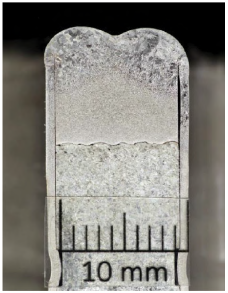
8. Macro examination: section the mock-up through the centre and the 4 exposed surfaces to be smoothed or etched. Use magnifications 10 X to 20 X (preferred 20 X for better visibility) to check the following:
• Minimum Leak Path (MLP)
• No cracking
• Complete fusion
• Complete penetrations
9. Calculate and record the actual expansion ratio for each tube. All values should be tabulated and compared to the target expansion ratio
10. In hydraulic expansion the applied pressure should cause the tube to take exactly the shape of the hole including the grooves and the imperfections or scratches (should they exist)
11. Mechanical roller must be clean as well and free from scratches or imperfections. Its lubrications, temperature and performance should be monitored during application.


Tubesheet hole preparation
Holes to be drilled in the dummy tubesheet which will be used in the mock-up should have the same quality and fabrication requirements applied as the actual tubesheet holes drilling. Below is a list of the main requirements:
- Preparing the tube holes in the mock-up tubesheet must be done using the same technique to be used for drilling the actual tubesheet to have a clear representative view about the quality of the drilled holes
- Holes should be free from radial or longitudinal scratches or imperfections
- The inner surface of the tubesheet holes should be in as machined conditions (no need for polishing)
- Tube holes and tube external surfaces should be cleaned
- Longitudinal scratches are of higher risk as it would create leak pass across the joint, please check the schematic sketch for elaboration
- The outer tube surface at the interface with hole should be also free from scratches or imperfections
Minimum Leak Path (MLP)
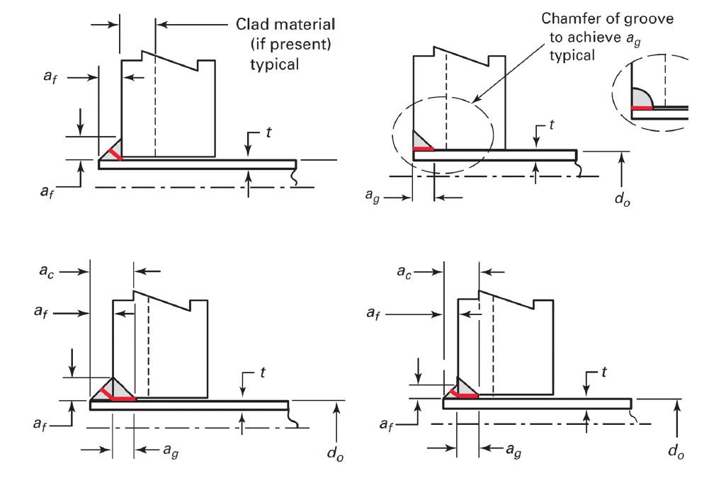
Minimum Leak Path (MLP) is an important parameter for the strength weld type tube-to-tubesheet joint. MLP is the minimum path where the media can leak and can be defined as the minimum distance in any direction from the root of the tube-to-tubesheet weld to the nearest surface.
MLP will depend on the type of the joint (fillet / groove / Fillet + groove / … etc.) and the actual shape of the applications (concave / convex / actual geometry / …etc.). In API 660, MLP is required to be no less than two-thirds of the nominal tube wall thickness. While in ASME BPVC section IX, it is required to meet the design, but there is no specific requirements for how to be identified.
The sketch below shows the MLP for different configurations of strength welded tube-to-tubesheet joints, colored red. In order to achieve the requirement of ASME Sec. IX, below are two demonstrative examples where the strength weld size is calculated as per rules of ASME BPVC Sec. VIII div.1 – UW.20 and then to be used for calculating the MLP length, as defined in the red lined marked sketches. Calculated values will be compared with the two thirds of the tube thickness as per API 660.
In these examples, the following material and design data is assumed and will be used for both examples:
- Tube material: carbon steel ASME SA 179
- Tubesheet material: carbon steel SA 266 Gr.2
- Tube DO: 19.05 mm, tube thickness BWG 14 (2.108 mm)
- Design temperature (to be used for getting the material allowable stresses): 200°C


Conclusion
A mock-up of tube-to-tubesheet assembly is a vital requirement to achieve good quality, long life joints. The successful mock-up will represent the actual conditions of the production joints and provide required inputs to control all essential and important parameters controlling the quality of the joints depend on many aspects covering the dimensions control, tools to be used, procedure and sequence to be applied, quality checks and testing. The mock-up should be a reference point in the ITP (Inspection and Test Plan) of the exchanger.
Users and owners should incorporate the application of a mock-up to ensure that detailed procedure is well-developed and reviewed including all the aforementioned aspects in addition to draft for the final report form.

About the author
Baher Elsheikh is a Mechanical Engineer at SAbIC. He has twenty years of experience in the engineering, reliability, construction, commissioning and inspection management of pressure equipment, piping systems, fired heaters, and power boilers.

