

Heat exchangers have been with us for more than a century. Over the years material science, simulations and other technological enhancements have dramatically improved their performance, but the basic functional structure has remained mostly unchanged.
However, due to new technological developments, thermal loads are growing and parasitic loads are decreasing, making the need for further heat exchanger optimization more pressing. This trend has set the engineering world on a quest to develop new ways of boosting efficiency.
By Kirill Volchek, Chief Technology Officer at Oqton, and Stephen Pfau, Associate Additive Manufacturing Research Engineer at the University of Dayton Research Institute
New research shows that a structure called a gyroid could be the answer. This lattice-like shape of the triply periodic minimal surface (TPMS) family features a very high surface-to-volume ratio that results in highly efficient heat transfer.
While TPMS-gyroids show great potential, adoption still lags due to challenges posed by their manufacturing. With the aim to explore this area, the University of Dayton Research Institute launched a project to redesign an existing fuel cooled oil cooler (FCOC) heat exchanger. They collaborated with Oqton to design and prepare the device for printing with 3DXpert, an industrial additive manufacturing software.
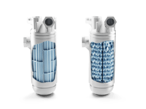
Keeping the housing the same, the new design replaced traditionally drawn tubes with a U-shaped structure filled with conformal TPMS-gyroids. Once finalized, the design should withstand temperatures between 139°F (59.4°C) and 165°F (74°C) at the fuel inlet, and a fuel flow rate ranging from 303 lbs/hr (137.2 kg/hr) to 3375 lbs/hr (1530.8 kg/hr). The oil inlet is designed to withstand 240°F (115°C) to 320°F (160°C) with the oil flow rate ranging from 2010 lbs/hr (907.18 kg/hr) to 3350 lbs/hr (1519 kg/hr). The working conditions are under 40 psi.
What is a TPMS gyroid?
A TPMS is a structure found in nature, for example in butterfly wing scales, that is mathematically defined by implicit equations. The structure offers a number of advantages for designing higher-performing systems, like high stiffness-to-mass ratio and high energy absorption, making them valuable in automotive, aerospace, and many other industries. Yet TPMS poses challenges to traditional manufacturing methods due to its curvature and interlacing lattice structure.

From a thermal perspective, a TPMS is a good candidate for heat exchangers because of its high surface area-to-volume ratio. The most common types used for heat exchanger cores are gyroid, diamond, and Schwartz structures. In addition, a TPMS-gyroid surface divides the design space into two separate domains that do not interfere with each other. In a two-fluid heat exchanger, gyroids can be used to design the channels that separate the fluids with the interface of the channels being a thin, printed wall.
The industry has recently turned up its focus on the potential of TPMS structures for heat exchangers with researchers working to identify the optimal parameters, including gyroid types, wall thickness, and channel diameters. Some use computational simulations to determine the performance of the gyroid (Weighong et al., 2020), while others printed prototypes using laser powder bed fusion (Mahmoud et al.,2023) and found these heat exchangers outperformed conventional designs.
Benefits of 3D printing for heat exchangers
TPMS structures are a prime example of a design novelty that is impossible without 3D printing. But the advantages of using additive manufacturing technology don’t stop at these geometries. Engineers have developed a set of unique design capabilities described as Design for Additive Manufacturing, or DfAM, that improve part performance in ways that were previously difficult to achieve. For example, topology optimization can be carried out to deliver the lightest possible part whilst maintaining critical functional requirements like strength and stiffness.
In addition, materials used for metal 3D printing are novel and often optimized for certain applications. Aluminium alloys, pure copper or copper alloys are a perfect fit for heat exchangers because of their high thermal conductivity. Beyond specialized design techniques and materials, additive manufacturing delivers significant time and cost savings. Fabricating a complex device with several components using traditional manufacturing methods comes with many technical challenges. The components must be individually fabricated, brought together, and assembled in a process that is lengthy and tedious.
3D printing makes development and fabrication much faster, and consequently cheaper because many, if not all, parts of an assembly can be printed together. The shorter lead times have monumental implications. Rapid iteration has become financially viable, and subsequently, manufacturers can pick up the pace of innovation. Because it’s faster to produce a part, we can afford to test various designs before settling on the optimal solution.
Putting TPMS structures to the test
Research developments coupled with new DfAM capabilities have prompted the University of Dayton Research Institute to put TPMS structures to the test. In 2022 they started a project with the aim to create a 3D-printed replacement for an existing shell and tube heat exchanger. UDRI collaborated with Oqton to create this novel design by leveraging their software, 3DXpert, which combines design tools for additive manufacturing and build preparation tools to generate instructions for 3D printing.
Several innovations were achieved in the process of redesigning the heat exchanger:
- Heat transfer enhancement with gyroid structures that replace the original cooler tubes.
- Automatically sealing opposite fluid domains (oil and fuel) with gyroid structures.
- Better flow path from top to bottom and back to the top achieved with a gyroid that follows the U-shape conformally.
- Different sizing of fluid domains to account for different viscosity of the fuel and the oil.
- A dedicated manufacturing (slicing) technology for thin walls that streamlined the manufacturing process.
Prototypes of the heat exchanger have been printed and the design is now undergoing improvements. However, valuable new capabilities and tools have already been developed as part of this project that will facilitate leveraging gyroids for heat exchange. To better understand the milestone of this redesign, let’s first examine how the conventional heat exchanger functions.

The role of oil-fuel heat exchangers
The primary purpose of the FCOC is to cool an aircraft’s engine oil. As the engine operates and generates heat, oil that circulates throughout the engine and lubricates parts absorbs some of the heat. If the oil becomes too hot, it can break down resulting in engine damage.
The FCOC prevents that by transferring the excess heat from the oil to the fuel. As a result, the oil temperature remains at a safe level. In addition to cooling the oil, the heat exchanger also preheats the fuel. Jet fuel can become very cold, especially at high altitudes, and this can lead to problems like fuel gelling or icing. The heat exchanger transfers heat from the oil to the fuel, helping avoid these issues.
By cooling the oil down to the correct operating temperature and preheating the fuel, the heat exchanger increases the overall efficiency of the aircraft engine. Proper oil temperature ensures optimal lubrication, which in turn reduces friction and wear on engine parts. At the same time preheated fuel burns more efficiently, providing the best combustion and power output.
The ins and outs of designing gyroids for heat exchange
The most important innovation achieved in this project is the use of gyroids as the heat exchange body. Keeping the outer shell design, we designed a U-shape flow path to replace the original 192 straight tubes. The space of the flow path was filled with a double TPMS-gyroid that forms the channels through which the fluids, oil and fuel, flow separately.
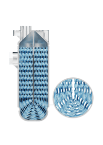
By improving the flow path from top to bottom and back to the front of the heat exchanger, the gyroid was made conformal, or following, the U-shape. Because the two liquids used in the heat exchanger have different viscosity, it was necessary to adjust the hydraulic diameter of their respective flow paths to optimize the pressure drop. As a result, the channels of the gyroid had two different sizes. Software played a vitally important role in the execution of the design.
Complex geometries like gyroids structures are impossible to create with traditional CAD tools as those use Boundary Representations to model shapes. TPMS structures are modelled with implicit equations and it’s necessary to use software with implicit modelling capability to use them in 3D design (see box on the right). 3DXpert allows users to design with both CAD and implicit functions, making it very well-equipped for the design of a heat exchanger with gyroids. In addition to the challenge of generating a 3D model of a TPMS structure, the conformal U-shape gyroid requires sophisticated software capabilities.
The new heat exchanger design also features windows to enable powder removal. In a previous project where the University of Dayton Research Institute had printed an entire heat exchanger as a single part, it was impossible to fully clean the powder and cling-on agglomerates from its surfaces. Informed by this experience, the current heat exchanger has special cleaning windows. Manufacturing such a heat exchanger comes with a different set of challenges.
Such complex parts are notoriously difficult to print with most workflows requiring that users convert the 3D model to an STL file for printing. With an elaborate model like a heat exchanger, the resulting STL files are simply too big for many computers to process, which often leads to delays in manufacturing or data integrity loss. Because 3DXpert integrates design capabilities with print control, the entire process was done without an STL. Simplifying the workflow in this way is critical in the future as parts are only going to get more complex as we move forward.
Additively manufactured thin walls
The second major innovation of the project was the ability to successfully additively manufacture thin walls – a challenge many engineers are familiar with. Very thin walls made with aluminium alloys, a material often used for heat exchangers, tend to leak, or warp while being printed with standard parameters. To make matters worse, high productivity parameters tend to overheat such thin geometries and this may crash a build.
To overcome this challenge, a new slicing and hatching approach was developed that resulted in an optimal wall thickness. Instead of using the boundaries as the origin for the scan path generation, we used the medial axis of the gyroid. With dedicated algorithms, we offset from the axis to get a consistent distance from the centre, allowing optimal thermal conditions during printing.
A designated heat exchanger application to streamline the design
Creating a heat exchanger with complex geometries usually requires a profound understanding of additive manufacturing processes and mastering multiple 3D printing software solutions. The complexity of this process is a barrier for manufacturers who want to develop higher-performing heat exchangers.
The 3DXpert team developed a dedicated heat exchanger application to streamline the design and manufacturing of these devices, making them more accessible to more organizations. The heat exchanger application uses computational, or generative design, and enables users to:
- Create inlets and outlets with automatic plug generation for each medium.
- Generate complex arrays of channels for direct feed into the TPMS structure.
- Estimate the efficiency coefficient with the analysis tools.
- Iterate quickly to find the best design.
One step closer to manufacturing high-efficient heat exchangers faster
New opportunities to harness additive technology for part optimization are constantly emerging – but fabrication can be a challenge. Software like 3DXpert will play an increasingly important role in helping create higher-performing parts such as heat exchangers with TPMS structures. Just five years ago these geometries were impossible to make. Today they’re used to design compact heat exchangers, with high efficiencies, shrinking the form factors, and improving their performance. The heat exchanger design started as part of this project is ongoing, but it is already evident that gyroids hold great promise for the future of thermal exchange and dedicated software solutions will help manufacturers leverage them.
What is Implicit Modeling and how does it help us build complex structures?
Solid modeling took the CAD world by storm in the 1990s. Since then, design software can tell where material exists in the 3D space using mostly Boundary Representation (B-Rep), which uses the edges and vertices of surfaces and their geometrical definition. This method is used for most mechanical design tasks.
However, B-Reps struggle with complex designs like a heat exchanger with a TMPS structure. To create the gyroids we used Implicit Modeling, a method which relies on mathematical equations to define shapes. Those equations determine if a given point in space F (X,Y,Z) is inside the volume – negative value, on the boundary – zero value, or outside of the volume – positive value. This allows us to easily formulate complex structures, even with millions of lattice-like cells that may be as small as your manufacturing software allows.
About the authors
 Kirill Volchek is the CTO for 3DXpert and Oqton. He has 30 years of experience as a software engineer in developing CAD/CAM systems. For the last eight years, Kirill has specialized in software for additive design and manufacturing.
 Stephen Pfau is a Research Engineer at the University of Dayton Research Institute, with over five years of experience in additive manufacturing, with a focus in metal laser powder bed fusion.
References
Mahmoud, D., Tandel, S.R.S., Yakout, M. et al. Enhancement of heat exchanger performance using additive manufacturing of gyroid lattice structures. Int J Adv Manuf Technol 126, 4021–4036 (2023). https://doi.org/10.1007/s00170-023-11362-9
Weihong Lia, et al. Bioinspired heat exchangers based on triply periodic minimal surfaces for supercritical CO2cycles. Applied Thermal Engineering 179:115686 (2020). https://doi.org/10.1016/j.applthermaleng.2020.115686
About this Featured Story
This Featured Story was first published in Heat Exchanger World Magazine in July 2023. To read more Featured Stories and many other articles, subscribe to our print magazine.
Featured Stories are regularly shared with our Heat Exchanger World community. Join us and share your own Featured Story on Heat Exchanger World online and in print.