
In my previous article published in Heat Exchanger World’s May issue, I had elaborated on different TEMA code shell and tube heat exchangers with the pros and cons for each. Here, we will look into thermal design and optimization of S&T heat exchangers. First, we will revisit critical heat exchanger parts and their significance in thermal design.
By Mihir M. Patel – Author of Mihir’s Handbook of Chemical Process Engineering
Tubes
Exchanger tubes are commonly available with either a smooth or finned outside surface. Selection of the surface type is based on applicability, availability, and economics. The conventional shell and tube exchanger tubing has a smooth surface. This is readily available in any material used in exchanger manufacture and in a wide range of wall thicknesses. This type of tubing is suitable for all shell and tube exchangers.
Tube length
The selection of tube length is affected by availability, site preference, and economics. Tube lengths up to 7.3 m (24 feet) are readily obtainable worldwide. Longer tubes (up to 12.2 m (40 feet) for carbon steel and 21.3 m (70 feet) for copper alloys) are available. However, either 4.9 m (16 foot) or 6.1 m (20 foot) tube length is a common refinery or chemical plant preference. Standard tube lengths: 6 ft (1.83 m), 8 ft (2.44m), 12 ft (3.66 m), 16 ft (4.87m), 20 ft (6.1 m), 24 ft (7.32 m)
Tube diameter and wall thickness
Exchanger tubing is supplied on the basis of a nominal outside diameter (OD) and either a minimum or average wall thickness. For exchanger tubing, the outside tube diameter is fixed. The inside diameter varies with the nominal wall thickness and wall thickness tolerance. Tube ODs range from small tubes of ½” to 2” size. Usual tube OD is ¾” chosen. Tema gives eight tube diameters: 9.525mm, 12.7mm, 15.875mm, 19.05mm, 25.4mm, 31.75mm, 38.1mm & 50.8mm. Note that smaller tube ODs create turbulence which is much desired, however, pressure drop and supporting lengths also need to be looked into.
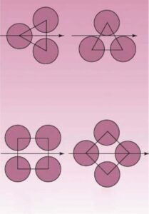
Tube layout
There are four types of tube layouts with respect to the shell side cross flow direction between baffle tips: square, rotated square, triangular and rotated triangular. Use of the triangular layout is preferred for all exchangers (except reboilers with a heat flux exceeding 19,000 W/m2 (6,000 Btu/hrft2) with the shell side fouling factors of 0.00035 m2 °C/W (0.0020 hrft2 °F/Btu) or less, provided the deposit can be cleared using chemical cleaning).
Square or rotated square tube layout should be specified for all shell and tube exchangers when the shell side fouling factor is over 0.00035 m2 °C/W (0.0020 hrft2 °F/Btu) whenever mechanical cleaning of the outside tube surface is required, or when requested by the end user. Square or rotated square tube layout is also required for reboilers with a heat flux exceeding 19,000 W/m2 (6,000 Btu/hrft2).
Tube pitch
Tube pitch (Pt) is defined as the shortest distance between two adjacent tubes. TEMA specifies a minimum tube pitch of 1.25 times the tube OD (do). It is preferred to employ the minimum recommended tube pitch, because it leads to the smallest shell diameter for a given number of tubes. However, in exceptional circumstances, the tube pitch may be increased to a higher value, for example, to reduce shell-side pressure drop.
- The selection of tube pitch is a compromise between a
- Close pitch (small values of Pt/do) for increased shell-side heat transfer and surface compactness, and an
- Open pitch (large values of Pt/ do) for decreased shell-side plugging and ease in shell-side cleaning.
- Tube pitch Pt is chosen so that the pitch ratio is 1.25 < Pt/do < 1.5
- When the tubes are too close to each other
(Pt/do less than 1.25), the header plate (tube sheet) becomes too weak for proper rolling of the tubes and cause leaky joints.
- When the tubes are too close to each other
- Tube layout and tube locations are standardized for industrial heat exchangers.
- However, these are general rules of thumb and can be “violated” for custom heat exchanger designs.
The number of tubes depends on
i) Fluid Flow rates
ii) Available pressure drop
Number of tubes are selected so that:
- Tube side velocity is between 0.9 to 2.4 m/s for liquid service
- Shell side velocity is between 0.6 to 1.5 m/s for liquid service
- Lower velocity is to limit fouling while upper velocity is to limit erosion
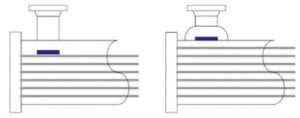
Cross baffles
Cross baffles support the tubes; restrain tube vibration and direct fluid flow on the shell side. Three types of baffles are generally used: segmental, double segmental, and rod baffles. ‘Baffle cut’ defines the segment of the baffle “cut” away to provide for fluid flow past the chord of the baffle.
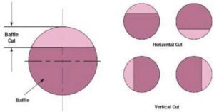
For segmental baffles, this is expressed as the ratio of the segment height to shell diameter in percent. The cut-out portion is usually from 20 to near 50 % of open shell area. ‘Baffle pitch’ is the longitudinal spacing between baffles, specified to the nearest 6 mm (1/4 inch).
The maximum baffle pitch is a function of tube size and metallurgy and, for no change of fluid phase, it is also a function of shell diameter. If there is no change of phase in the shell side fluid, the baffle pitch should not exceed the shell inside diameter. The minimum allowable baffle pitch is 20% of the shell inside diameter or 2 inches (50 mm), whichever is greater.
Summary of when to use each baffle type is as below:
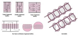
- Single Segmental Baffles
– Standard Arrangement
– Inexpensive
– Used if neither ∆P nor tube vibration is a problem - Double Segmental
– Used if ∆P must be limited and tube vibration is not a problem - NTIW (No Tubes in Window)
– Used if ∆P must be limited and tube vibration is a problem - Triple Segmental
– Provides lower ∆P than Single or Double Segmental
– Has a large unsupported tube span
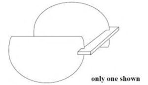
Seal strips
Seal strips are flat strips of metal (or tie rods) that extend the length of the shell in order to prevent the shell-side fluid from flowing through the clearance between the tube bundle and the inner wall of the shell.
The seal strips are located between the baffle chords of adjacent baffles, in the clearance between the tube bundles and the shell. The impingement plate or other protection devices are normally installed on the top row of tubes under the shell inlet nozzle or in shell side inlet nozzles to protect the bundle against impingement by the incoming fluid when the fluid:
(a) is condensing, (b) is a liquid vapor mixture, (c) contains abrasive material, or (d) is entering at high velocity.
In addition, TEMA requires bundle impingement protection when nozzle values of ρV2 exceed: 2230 kg/ms2 (1500 lb/fts2) for noncorrosive, nonabrasive, single phase fluids. 744 kg/ms2 (500 lb/fts2) for all other liquids, including liquid at its boiling point.
Shell & tube passes
Shell pass: Usually this is one in “E” type. Can be two in “F” types shells. Tube pass: Always choose this in even numbers up to 10 maximum. Odd numbers have more complicated mechanical stresses. Tube passes increase is done to increase tube side velocity for more turbulence & lower fouling, however, we need to consider pressure drop which increases also.
")
Fluid allocations
Below table provides industry practice in fluid allocations. Notes on Table 1:
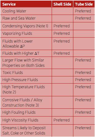
- Condensing Steam is normally passed through the tubeside.
- If the temperature change of one fluid is very large it should pass through the Shellside if more than one tubepass is required (>170-195°C or 300-350°F). This minimizes the construction problems caused by the thermal expansion.
- If one of the fluids is clean but is somewhat corrosive, the fluid is normally passed through the tubeside since it is typically easier to change the tubes to the correct alloy.
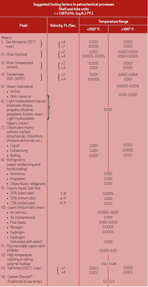
Fouling factors
Typical industry fouling factors are shown below from Mihir’s Handbook of Chemical Process Engineering.
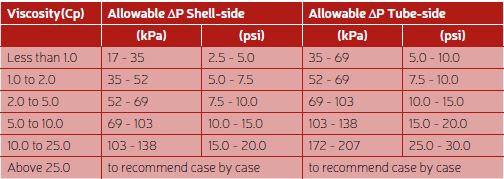
Pressure drop allowances
The following guidelines may be used as starting points for setting “clean” fluid pressure drop
allowances for the normal shell & tube design flow rate. Note that pressure drops for gaseous or vacuum services are usually considerably lower.
Thermal design:
We will elaborate on HTRI, which is a very well established and relied upon heat exchanger design software in industry. In HTRI, one can select from several modes:
i) Rating (known duty and geometry), checking the performance of a specified heat exchanger
ii) Simulation (unknown duty and known geometry), predicting the performance of a specified geometry for a given set of inlet (or outlet) condition
iii) Design (known duty and unknown geometry), performing the design for a specified duty
When one has to plan heat exchanger geometry, remember that the object is to maximise the B stream flow fraction and minimise leakage stream flow fractions. In actual practice, it is not possible or necessarily desirable to eliminate leakage streams completely because clearances are required to construct the heat exchanger.
While Performing optimization, efforts should be made to maximize the B-Stream (Cross flow stream). This is normally 60-80%. C-Stream is significant in pull through bundle exchangers and can be reduced by use of sealing strips. A-stream effects more on pressure drop than heat transfer.
Tips on thermal design optimization:
a) Rating of S&T heat exchanger design
- If the output of the rating analysis is not acceptable, a geometrical modification should be made
- If the required amount of heat cannot be transferred to satisfy specific outlet temperature, one should find a way to increase the heat transfer coefficient or increase exchanger surface area
- One can increase the tube side heat transfer coefficient by increasing the fluid velocity – Increase number of tube passes
- One can increase the shell side heat transfer coefficient by decreasing baffle spacing and/or baffle cut
- One can increase the surface area by
- Increasing the heat exchanger length
- Increasing the shell diameter
- Multiple shells in series
- If the pressure drop on the tube side is greater than the allowable pressure drop, then
- the number of tube passes can be decreased or
- the tube diameter can be increased which may result to
- decrease the tube length – (Same surface area)
- increase the shell diameter and the number of tubes
- If the shell side pressure drop is greater than the allowable pressure drop then baffle spacing, tube pitch, and baffle cut can be increased or one can change the baffle type.
b) Roadmap to increased heat transfer
- Increase heat transfer coefficent
- Tube Side
- Increase number of tubes
- Decrease tube outside diameter
- Shell Side
- Decrease the baffle spacing
- Decrease baffle cut

Table 3: Recommended HTRI flow stream values (Source: Mihir’s Handbook of Chemical Process Engineering)
- Tube Side
- Increase surface area
- Increase tube length
- Increase shell diameter → increased number of tubes
- Employ multiple shells in series or parallel
- Increase LMTD correction factor and heat exchanger effectiveness
- Use counterflow configuration
- Use multiple shell configuration

c) Roadmap to reducing pressure drop
- Tube side
- Decrease number of tube passes
- Increase tube diameter
- Decrease tube length and increase shell diameter and number of tubes
- Shell side
- Increase the baffle cut
- Increase the baffle spacing
- Increase tube pitch
- Use double or triple segmental baffles
Typical output summary from software for a condenser is shown below. Note the “Flow Fractions” in right bottom corner which are the flow streams. One can figure out which side needs optimization by looking at the “Thermal Resistance %” in lower left hand corner of output summary. The side having highest thermal resistance needs more optimization.
")
About the author
 Mihir M. Patel is a chemical engineer and project management professional (PMP®) from PMI, USA, as well as a TUV SUD certified functional safety professional. He has been practicing chemical engineering for over 36 years in the chemical process industry. Patel now shares his knowledge and experience through the format of published handbooks and training courses for chemical engineers.